Create Your Structured Cabling Solutions

Have troubles in vertical or horizontal cable management in your data center? Confused at the cables’ destinations and start points? With slack cables hanging here and there in server rack, blocking and pathway? Well, all these issues brought by point-to-point cabling will become the thing of the past as the structured cabling comes into being.

What Is Structured Cabling?

Before the 1990s, data and cabling system were proprietary which means they were vendor specified, each vendor had his own cabling system design and it was hard to have products from different vendors to work together. In the mid 1980s, the EIA was asked to develop a specification that would encourage structured standardized cabling. In 1991 the TIA published the first version of the commercial building telecommunications cabling standard, better known as TIA/EIA-568.

In the United States, we follow TIA/EIA-568-C as the structured cabling standard. It covers subsystems of structured cabling, installation methods and practices, connector and pin assignments, media types and performance specifications for horizontal and backbone cabling, connecting hardware performance specifications, recommended topology and distances, and the definition of cable elements (horizontal cable, cross-connects, telecommunication outlets, etc.)

structured cabling solution

How to Design Your Own Structured Cabling Solution

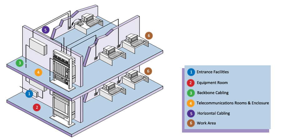
Presume that we have an empty building of four storeys, we need to design a structured cabling solution for different uses in it. One solution we must apply, also one of the subsystems of structured cabling, is horizontal cabling which can not be skipped in each floors. Horizontal cabling is the cabling that extends from horizontal cross-connect or main cross-connect to the work area and terminate in telecommunications outlets. Horizontal cabling includes the following: 1.Cable from the patch panel to the work area; 2.Telecommunications outlets; 3.Cable terminations ; 4.Cross-connections(where permitted); 5.A maximum of one transition point; 6.Cross-connects in telecommunications rooms or enclosures.

Furthermore, to achieve the connection between different floors, we need the backbone cabling, also known as vertical cabling. We can adopt it to to connect entrance facilities, equipment rooms, and telecommunications rooms and enclosures. Backbone cabling consists of not only the cables that connect the telecommunications rooms, equipment rooms, and building entrances, but also the cross-connect cables, mechanical terminations, or patch cords used for backbone-to-backbone cross-connection.

The work area is where the horizontal cable terminates and wall outlets also called the telecommunications outlet. In the work area, the users and the telecommunications equipment connect to the structured cabling infrastructure. The work area begins as a telecommunications area and includes components such patch cables, modular cords, fiber jumpers, station equipment such as computers, telephones, fax machines and so on.

The telecommunications rooms and telecommunications enclosures are the location within the building where cabling components such as cross-connects and patch panels are located. These rooms are where the horizontal structured cabling starts from. The telecommunications room and enclosure may also contain networking equipment such as hubs, switches, routers, etc.

The equipment rooms is a centralized space specified to house more sophisticated equipment than the entrance facility or the telecommunications rooms. Most often, telephone equipment or data networking such as routers, switches, and hubs are located there. Backbone cabling is specified to terminate in the equipment room.

The entrance facility specifies the point in the building where cabling connects with outside world. All external cabling such as campus backbone, inter-building, and telecommunications provider should enter the building and terminate in a single point.

Digital data is growing faster than any other commodity and its importance to businesses of all types cannot be underestimated. To learn how you can use structured cabling to better manage your data center, contact the experts at FS.COM.

Key Components to Form a Structured Cabling System

Building a structured cabling system is instrumental to the high performance of different cable deployments. Typically, a structured cabling system contains the cabling and connectivity products that integrates the voice, data, video, and various management systems (e.g. security alarms, security access, energy system, etc.) of a building. The structured cabling system is based on two standards. One is the ANSI/TIA-568-C.0 of generic telecommunications cabling for customer premises, and another is the ANSI/TIA-568-C.1 of commercial building telecommunications cabling for business infrastructures. These standards define how to design, build, and manage a cabling system that is structured. Six key components are included to form a structured cabling system.

Six Subsystems of a Structured Cabling System

Generally speaking, there are six subsystems of a structured cabling system. Here will introduce them respectively for better understanding.

structured-cabling-system

Horizontal Cabling

The horizontal cabling is all the cabling between telecommunications outlet in a work area and the horizontal cross-connect in the telecommunications closet, including horizontal cable, mechanical terminations, jumpers and patch cords located in the telecommunications room or telecommunications enclosure, multiuser telecommunications outlet assemblies and consolidation points. This type of wiring runs horizontally above ceilings or below floors in a building. In spite of the cable types, the maximum distance allowed between devices is 90 meters. Extra 6 meters is allowed for patch cables at the telecommunication closet and in the work area, but the combined length of these patch cables cannot exceed 10 meters.

Backbone Cabling

Backbone cabling is also known as vertical cabling. It offers the connectivity between telecommunication rooms, equipment rooms, access provider spaces and entrance facilities. The cable runs on the same floor, from floor to floor, and even between buildings. Cable distance depends on the cable type and the connected facilities, but twisted pair cable is limited to 90 meters.

Work Area

Work area refers to space where cable components are used between communication outlets and end-user telecommunications equipment. The cable components often include station equipment (telephones, computers, etc.), patch cables and communication outlets.

Telecommunications Closet (Room & Enclosure)

Telecommunications closet is an enclosed area like a room or a cabinet to house telecommunications equipment, distribution frames, cable terminations and cross connects. Each building should have at least one wiring closet and the size of closet depends on the size of service area.

Equipment Room

Equipment room is the centralized place to house equipment inside building telecommunications systems (servers, switches, etc.) and mechanical terminations of the telecommunications wiring system. Unlike the telecommunications closet, equipment room houses more complex components.

Entrance Facility

Entrance facility encompasses the cables, network demarcation point, connecting hardware, protection devices and other equipment that connect to the access provider or private network cabling. Connections are between outside plant and inside building cabling.

Benefits of Structured Cabling System

Why do you need the structured cabling system? Obviously, there are many benefits for using the system. A structured cabling can standardize your cabling systems with consistency so that the future cabling updates and troubleshooting will be easier to handle. In this way, you are able to avoid reworking the cabling when upgrading to another vendor or model, which prolongs the lifespan of your equipment. All the equipment moves, adds and changes can be simplified with the help of structured cabling. It is a great support for future applications.

structured-cabling

Conclusion

From this article, we can know that a structured cabling system consists of six important components. They are horizontal cabling, backbone cabling, work area, telecommunications closet, equipment room and entrance facility. Once you split the whole system into small categories, the cabling target will be easier to get. As long as you keep good management of these subsystems, your cabling system is a success to be called as structured wiring.