Which Fiber Loopback Should I Use for My Transceiver?

In telecommunication, fiber loopback is a hardware designed to provide a media of return patch for a fiber optic signal, which is typically used for fiber optic testing or network restorations. When we need to know whether our fiber optic transceiver is working perfectly, we can use a fiber loopback cable as an economic way to check and ensure it. Basically, the loopback aids in debugging the physical connection problem of the transceiver by directly routing the laser signal from the transmitter port back to the receiver port. Since fiber optic transceivers have different interface types and connect different types of cables, it is not that simple to choose a right loopback for our transceiver. This post will be a guide on how to choose a right loopback cable for specific transceiver module.

Fiber Loopback Types and Configurations

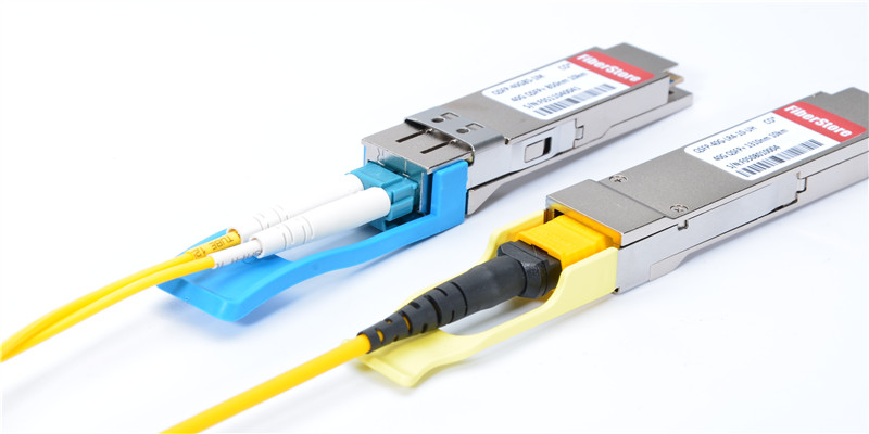
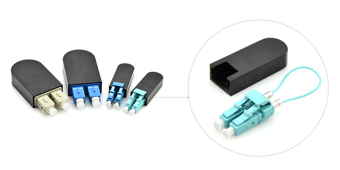
Before deciding which loopback cable to use, we should firstly know the structure and classification of fiber loopback cable. Generally, a fiber loopback is a simplex fiber optic cable terminated with two connectors on each end, forming a loop. Some vendors provide improved structure with a black enclosure to protect the optical cable. This designing is more compact in size and stronger in use. Based on the fiber type used, there is single-mode loopback and multimode loopback, available for different polishing types. According to the optical connector type of the loopback, fiber loopback cables can be divided to LC, SC, FC, ST, MTP/MPO, E2000, etc. In testing fiber optic transceiver modules, the most commonly used are LC, SC and MTP/MPO loopback cables.

lc&sc loopback cable
Figure 1: LC & SC Loopback Cable

The LC and SC loopbacks are made with simplex fiber cable and common connectors; it’s not difficult to understand their configurations. As for the MTP/MPO loopback, it is mainly used for testing parallel optics, such as 40G and 100G transceivers. Its configuration varies since the fiber count is not always the same in different applications.

8 Fibers MTP/MPO Loopback Cable Configuration

In a 8 fibers MTP/MPO loopback, eight fibers are aligned on two sides of the connector, leaving the central four channels empty. And the fibers adopt a straight configuration of 1-12, 2-11, 5-8, 6-7. The polarity channel alignment is illustrated in the following figure.

8 Fibers Loopback Polarity Channel Alignment
Figure 2: 8 Fibers Loopback Polarity Channel Alignment
12 Fibers MTP/MPO Loopback Cable Configuration

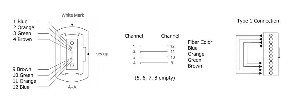
The only difference between the 12-fiber MTP loopback and the 8-fiber loopback is that the central four channels are not empty. Its alignment is 1-12, 2-11, 3-10, 4-9, 5-8, 6-7.

12 Fibers Loopback Polarity Channel Alignment
Figure 3: 12 Fibers Loopback Polarity Channel Alignment
24 Fibers MTP/MPO Loopback Cable Configuration

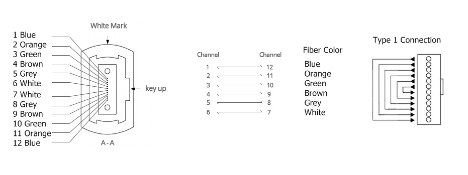
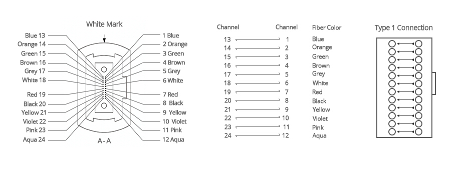
The 24 fibers MTP loopback also adopts type 1 polarity. Its alignment design is shown below.

24 Fibers Loopback Polarity Channel Alignment
Figure 4: 24 Fibers Loopback Polarity Channel Alignment
Which to Choose for a Specific Transceiver?

Considering the common features of the transceiver and the loopback, we should think about the connector type, polish type, and cable type when selecting a loopback for the transceiver. The selection guide for some mostly used transceiver modules is summarized in the following tables.

Table 1: Loopback choices for 10G SFP+ transceivers

Model Interface type Cable Type Suited Loopback
10GBASE-USR LC Duplex (PC) MMF

LC/UPC Duplex Multimode Fiber Loopback

10GBASE-SR LC Duplex (UPC) MMF
10GBASE-LR LC Duplex (UPC) MMF
10GBASE-ER LC Duplex (UPC) SMF

LC/UPC Duplex Single-mode Fiber Loopback

10GBASE-ZR LC Duplex (PC) SMF

Table 2: Loopback choices for 40G QSFP+ transceivers

Model Interface type Cable Type Suited Loopback
40GBASE-CSR4 MTP/MPO (UPC) MMF

8/12 Fibers MTP/UPC Multimode Fiber Loopback

40GBASE-SR4 MTP/MPO (UPC) MMF
40GBASE-PLRL4 MTP/MPO (APC) SMF

8/12 Fibers MTP/APC Single-mode Fiber Loopback

40GBASE-PLR4 MTP/MPO (APC) SMF
40GBASE-LR4 LC Duplex (PC) SMF

LC/UPC Duplex Single-mode Fiber Loopback

40GBASE-LR4L LC Duplex (UPC) SMF
40GBASE-ER4 LC Duplex (UPC) SMF
40GBASE-LX4 LC Duplex (UPC) MMF/SMF

LC/UPC Duplex Multimode/Single-mode Fiber Loopback

Table 3: Loopback choices for 100G QSFP28 transceivers

Model Interface type Cable Type Suited Loopback
100GBASE-SR4 MTP/MPO (UPC) MMF

8/12 Fibers MTP/UPC Multimode Fiber Loopback

100GBASE-PSM4 MTP/MPO (APC) SMF

8/12 Fibers MTP/APC Single-mode Fiber Loopback

100GBASE-LR4 LC Duplex (UPC) SMF

LC/UPC Duplex Single-mode Fiber Loopback

Table 4: Loopback choices for CFP transceivers

Model Interface type Cable Type Suited Loopback
40GBASE-SR4 CFP MPO/MTP (UPC) MMF

8/12 Fibers MTP/UPC Multimode Fiber Loopback

40GBASE-LR4 CFP SC Duplex (UPC) SMF

SC/UPC Duplex Single-mode Fiber Loopback

40GBASE-FR CFP SC Duplex (UPC) SMF
100GBASE-LR4 CFP SC Duplex(PC/UPC) SMF
100GBASE-ER4 CFP SC Duplex(PC/UPC) SMF
100GBASE-SR4 CFP MPO/MTP (UPC) MMF

24 Fibers MTP/UPC Multimode Fiber Loopback

Conclusion

This post discusses specific fiber loopback choices for some most commonly used fiber optic transceivers. For other transceiver modules that are not mentioned in this post, we can also know how to choose a suitable loopback for it by getting details about its interface type, physical contact and cable type.

Choose the Right Patch Cable for Your Transceiver Module

To a large extent, a fluent data transmission relies on the seamless transition between patch cables and fiber optic transceivers. As high bandwidth gradually dominates the market, patch cables and transceivers become much more essential to data transmission, especially for data transmission between the switches and equipment. But when you try to find the right patch cable for your transceiver, you may feel dazzling about the great variety of products. Don’t worry, this article will help you find the quickest way to choose the suitable product. But first, let’s have a look at the basic knowledge about patch cables and transceiver modules.

Overview of Patch Cables and Transceiver Modules

A patch cable or patch cord is an electrical or optical cable used to connect one electronic or optical device to another for signal routing. It is composed of an electrical or optic cable terminated with connectors on the ends. Optical patch cables are now widely used in data centers for data transmission. They have different fiber connectors including LC, SC, ST, FC, MTRJ, E2000, MU, MPO/MTP, etc. As for fiber types, there are also single-mode patch cables and multimode patch cables. Single-mode patch cables can further be classified into OS1 and OS2. While the multimode can be further divided into OM1, OM2, OM3 and OM4.

fiber-vs.-copper

Transceiver is a self-contained component that can both transmit and receive. It is often inserted in devices such as switches, routers or network interface cards which provide one or more transceiver module slot. Many transceivers types, such as SFP, X2, XENPAK, XFP, SFP+, QSFP+, CFP, etc. are used for various applications. The transceiver accepts digital signals from the Ethernet device and converts them to optical signals for transmission over the fiber.

Several Aspects to Consider
Transmission Media

Two kinds of transmission media can be found in the network. They are optic fiber cable and copper cable. Therefore, transceivers also have two types based on transmission media — copper based transceivers and fiber optic based transceivers. Copper based transceivers like 100BASE-T SFP, 1000BASE-T SFP are the commonly used types. They have a RJ45 interface to connect with the copper cables. Generally, cat 5, cat 6 and cat 7 cables attached with RJ45 connectors are typically linked to the copper based transceivers.

Compared with copper based transceivers, fiber optic transceivers support higher data rates for over 100 Gbps. The supported fiber patch cables are more complicated for selection. Usually single-mode and multimode fiber patch cables are used. But according to different transmission rates and transmission distance, further choices should be made.

Transmission Rate and Distance

It is known that data rate decreases as the transmission distance increases in fiber optic cables. Multimode fiber optic cables are often used for short distances due to the high cost of single-mode optical cables. But single-mode patch cables have better performance for different data rates in both long and short distances. Thus, if your transceiver supports high data rate over long distance, single-mode should be a better choice, and vice versa.

Transceiver Interface

Interfaces are also important to the selection of patch cables that match with transceivers. Optical transceivers usually use one port for transmitting and one port for receiving. Cables with duplex SC or LC connectors are typically employed to connect with this type of fiber optic transceivers. However, for BiDi transceivers only one port is used for both transmitting and receiving. Thus, simplex patch cables are used with BiDi transceivers.

Other high data rate transceivers like 40G/100GBASE QSFP+ often use MTP/MPO interfaces. They should be connected to the network with multi-fiber patch cords attached with MTP/MPO connectors. If these ports are used for 40 G to 10 G or 100 G to 10 G connections, fanout patch cables should be used.

transceiver-and-patch-cords

Conclusion

Knowing the transmission media, transmission data rate and distance, transceiver interfaces can give you a general direction of which type of patch cables should be chosen. Only matched patch cables and transceiver modules can provide better performance.

Fiber Optics Based on Multi Point Fiber Distribution Systems

Multi point distribution system is the broad wireless technology used to deliver voice, data, Internet, and video services. It has been allocated for that deliever broadband services in a point to point or point to multi point configuration to residential and commercial customers. As a result of the propagating characteristics of signals so that the systems use a cellular like network architecture, though services provided are fixed, not mobile.

In some cases fiber distribution systems have an ability to connect several remote sites to one base station. One common application is that the repeaters based on a major building and others building such as RF shielding areas and basement which all located in a few miles repeater building. A and the repeater use the head end. A multiple fiber optic transceiver assembly at the base station is commonly called a “head end” The distance end of the fiber is called “remote hub” equipment.

fiber distribution systems

We need to pay attention to that each fiber optic receiver output at the repeater site has individual pads to reduce the composite noise floor. For example, if used the 40dB, an additional 80 dB of combiner port-to-port isolation occurs. In real application, it is a good idea, including regard the taps at test point to read the RF levels. Just used for testing and protection. A similar system that when we used the WDM, if the numbers of fibers are reduced by 50% but a WDM must be added at each remote site and another WDM for each fiber added at the repeater site. In the 4 remote site example, it would be taking 8 WDM’s to operate all the fibers full duplex and 4 fiber optic transmitters would have to be 1550nm models. Then there also a point we need to be careful. Fiber optic transceiver is not frequency selective and the same unit can receive 1330 or 1550nm optical signals equally well. We also measured the noise performance and we are happy to inform you that in line with theory, optic splitters practically do not add any noise. No matter what output we tested, this means that your receiver connected to such network would also show very high quality readings.

When we use the fiber optic links in the fiber distribution system, sometimes we need fiber optical splitter to split the signal which carried. The systems designer has the choice of splitting either the optical or RF domain. The function of optical splitter is familiar to RF splitter. Other parts of the incoming fiber optic network are connected to the transmission of output, and the terminal device is connected and the another main part is its direct part. There are also splitters that divided the input into 2, 4 or more outputs. According to the structure and locations of fiber optic splitter, in the fiber optic network, we need different split ratios of splitter, such as 1×2, 1×4 and 1×8 splitter and so on. Moreover unused single mode fiber cable, specific products can see at 50m single mode, it also can strengthen the signal used for the RF over fiber systems between the connected buildings for data communication and spare fibers.

Optimistic about the Development of 40G and 100G Network Devices in the Future

In June of 2010, the IEEE 802.3 ba 40G/100G standard issued. The Standard Approval timeline for IEEE 802.3ba is depicted in the figure. It makes me looking good forward to its development in the future. Traditional 10G port modules usually adopt LC connector, they are connected by dual cores while 40G Ethernet specification requires 8 cores connections, just 4 cores used for transmitting and another 4 cores used for receiving. Better advice for 40G Ethernet is that the 12 cores fiber cabling solution, each channel has 4 special transmitting fiber and 4 special receiving fiber, middle 4 fibers remain free. 100G Ethernet solution requires to make 24 fibers, it divided into two 12 fibers, one for receiving and another for transmitting, and each of the array, middle 10 fibers used for transit traffic, the two fibers on the ends are setting free.

IEEE

Several years ago, once we met customers who wants to know if our transceiver modules support 40G and 100G ports, we will tell them that some suppliers who launched the 40G and 100G optical transceiver module are mostly based on previous 40G/100G draft, they are not the standard ports, and different vendors exist connection trouble, so we are all not sure. But nowadays, with the mature development of 40G and 100G cores, many supplier launched them their own fiber optic transceiver. In the field of 40G and 100G, device manufacturers adopt the advantage of long term evolution and 40G network which focus on 100G network communication equipment. In fact, it is the estimated results that operator who faces with 40G and 100G network. In the next year, 40G long distance transmission network market supplier will launch the 100G network transmission devices, it will bring a big challenge to the operator. The fact dedicates that fiber optic device operators will do double budgets for current production to meet the demand of the future developments.

In the network market, WDM devices are quite popular between global operators. It makes the sales of the products to improve highly. Adjustable and pluggable optical transceiver module, such as XFP, become quite popular in the ROADM network market, it will broaden the network scopes of operators, includes IP/Ethernet CMTs, OLTs FTTH, DSLAMs. As for the 10G SFP+ transceiver module, such as 10G SFP+ 1550nm 80km, it sales reached three times, they are primarily applied into 10G Ethernet and 8G/16G fiber channel. The main reason why development speed of 100G fiber network faster than 40G is that the price of 100G network is lower than 40G, so the much lower LR4 modules will have a great future. Related product: SFP-10G-LR, see at the figure.

lr

Faced with the rapid progress of 40G and 100G optical transceiver modules, Fiberstore also research its brand. Including production and sales of 40G and 100G. Fiberstore has high quality and reasonable price. Our fiber optical transceivers all pass certification. If you have fiber optical transceivers needs, Fiberstore will be your first choice.

How to Achieve Long Distance Transmission by Fiber Optic Transceiver

Recently we met a big project that involved the network channel installation about digital optical transmission equipment, in fact, it is not so complex as the organization network ways, just we can use with SDH and downward access with switches over backbone line, but because of the SDH equipment covers all the site in the progress of construction, so it need to be solved for long distance network connections by another way. Fortunately, we have much experiences in using fiber optic transceiver, this page we will introduce the application of fiber optic transceiver in the network construction progress which combines with this experience.

1. Multimode fiber optic transceiver and multimode fiber optic cables

Fiber optic transceiver is an ethernet transmission device that can exchange the light signal and electrical signal, fiber optic cables that can transfer data over network can be divided into multimode fiber optic cables and single-mode fiber optic cables, fiber core diameter of multimode fiber cable is 50~62.5 μm,and the single-mode fiber cable core diameter is 8.3 μm. In fact, these data are not intuitive for us, we can judge it only by colors, the multimode fiber pigtail‘s color is orange and the single-mode fiber cable is yellow. From the network applications, because of multimode fiber optic cable can transmit for not tool long distance, it just can be used between the buildings, but because of the price is relatively cheap, so there are still some people like to use it.

2. Single-mode fiber optic transceiver series

With the development of technology, this phenomenon that single mode fiber cables applied into the long distance network installation is more and more popular, nowadays many customers use fiber optic transceiver directly, just we call it FTTH (fiber to the home), and  these different types of fiber optic transceivers we will introduce to you all based on single mode fiber cables.

Dual Fiber Single Network Port

The dual fiber single network port fiber optic transceiver just use two fibers, a fiber is used to receive and another is used to transmit. A group of fiber optic transceivers can achieve the exchange of electrical signal and light signal. The network device may a switch, also may a server, well, we can see the fiber optic transceiver as PC, which connected with the switch is straight through cable, and with the server is cross cable. With the development of technology, the fiber optic transceiver ports have been generally made adaptive mode (automatic matching cross-line and direct line), it also bring conveniences to the projects.

Single Fiber Single Network Port

With the continuous development of business, we are faced with an unavoidable problem that the shortage of fiber resources. Some companies want to connect the network but there is only a fiber, it is time to use the single mode fiber optic transceiver, it means that receive and transmit signal over a fiber, this product use WDM technology, related product: passive cwdm mux (shown as the figure). The wavelength usually are 1310nm and 1550 nm, and the 1310 nm stands for transmission, and the 1550 nm stands for receiving.

cwdm

Single Fiber Dual Ethernet Port

With the development of business, some units put forward higher requirements, for example, we organized network for one bank, he asked us to provide two Ethernet lines to separate from. it needs mature and safe fiber optic transceiver device technology, in order to simply the cost of fiber optic devices and achieve the networks over one fiber, we try our best to save the fiber sources. Our solution is that using 10/100 m adaptive port devices, access into the Ethernet link which can reach 60 km, also keep it to support network management functions.

3. Gigabit fiber optic transceivers and integrated optical interface switches

The advantages of using fiber optic transceiver to connect the network, not only stable, but also it has fast speed, 100M full duplex and even 1000M duplex. For example, there is a Engineering machinery manufacturing enterprise, they use the 100M link to network at the beginning, but due to the requirements of the developments of business, we need to provide higher speed to them, fortunately, the progress of the technology provide good products for us, just gigabit fiber cable, from the appearances of fiber cable, it has no differences with 100M fiber transceivers. Yeah, the fiber optic transceiver we used can be directly plugged into the original power supply unit box, which just needs to change the fiber optic transceiver and then upgrade the bandwidth from Fast to Ethernet. Otherwise, we found that the education industry prefer to use an integrated gigabit fiber interface on the switches.