MTP Specifications and Deployment for 40GBASE-PLRL4 QSFP+

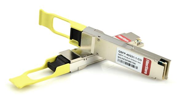
Commonly, QSFP+ transceiver designed with LC interface works with single-mode fiber for long distance application, while QSFP+ transceiver with MTP/MPO interface is used over multimode fiber for short distance transmission. For instance, 40GBASE-ER4 QSFP+ is designed with LC duplex interface, and it supports maximum transmission length of 40 km over single-mode LC duplex fiber; 40GBASE-SR4 QSFP+ with MTP/MPO interface supports a transmission distance no more than 150m over multimode fiber. However, in order to meet user’s diverse needs in real applications, some 40G transceivers are designed not following this rule, like 40GBASE-PLRL4 (parallel LR4 Lite). This transceiver is with MTP/MPO interface design but is used over single mode fiber for long distance transmission. This article will introduce the MTP/MPO specifications for this transceiver and its deployment cases.

40GBASE-PLRL4 transceiver

MTP Specifications for 40GBASE-PLRL4 QSFP+

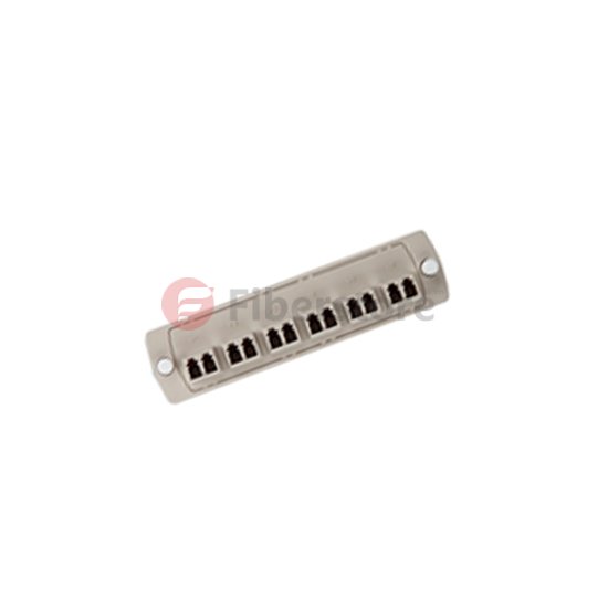
QSFP-40G-PLRL4 transceiver uses MTP-12 interface to achieve parallel transmission, supporting maximum data links up to 1.4 km. The cable type required for 40GBASE-PLRL4 is an APC (angle polished connector) single-mode MTP-12 cable. The cable is similar to the 40G-SR MTP or MPO, with the only change being the use of single-mode fiber. UPC (ultra-polished connector) is another type of connector for MTP-12 cables, but it is not suited for single-mode fiber in the market. APC is the only available type for single-mode MTP-12 fiber. The MTP-12 connector plugged into the QSFP-40G-PLRL4 transceiver carries the 40G signal over only 8 of the 12 fibers, remaining four fibers unused, and these four can optionally be not presented in the cable for an economic reason. The used 8 fibers are mapped as 4x10G Tx and Rx pairs. In addition, the MTP cables connected to QSFP-40G-PLRL4 transceiver can be either MTP trunk cables or MTP splitter cables.

Deployment of 40GBASE-PLRL4 QSFP+

The QSFP-40G-PLRL4 is optimized to guarantee interoperability with any IEEE 40GBASE-LR4 and 10GBASE-LR. So when the link for 40G network and 10G to 40G migration is less than 1.4 km, it will be very appropriate to use 40GBASE-PLRL4 QSFP+ transceiver with single-mode MTP cables.

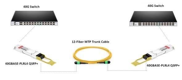
In the first case, you can choose an MTP trunk cable together with the 40GBASE-PLRL4 QSFP+ module for direct 40G connection. The following picture shows two 40GBASE-PLRL4 QSFP+ transceivers connected by a single-mode 12-fiber MTP trunk cable.

40GBASE-PLRL4 QSFP+ for 40G connection

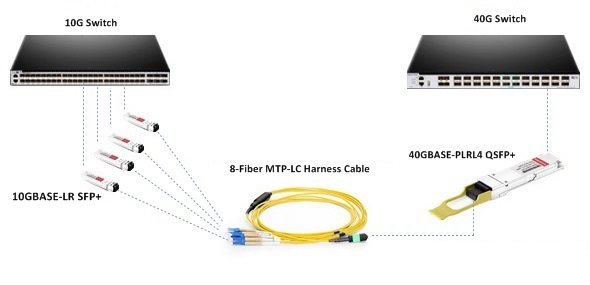
In the second case, you can simply use an 8-fiber MTP to 4xLC duplex harness cable with one 40GBASE-PLRL4 QSFP+ and four 10GBASE-LR SFP+ to achieve 10G to 40G.

40GBASE-PLRL4 QSFP+ for 10G to 40G migration

You can see in the above two cases, MTP cable plays an important role and due to the special requirements of 40GBASE-PLRL4 for single-mode MTP fiber, it is necessary to choose the right MTP products connected to this 40G QSFP+.

Conclusion

40GBASE-PLRL4 QSFP+ module has special interface design which can be only compatible with single-mode MTP connector. During the deployment of 40GBASE-PLRL4 QSFP+ module, selecting proper MTP assemblies are essential to successfully accomplish the link. FS.COM is a professional fiber optic transceiver vendor and MTP product manufacturer, supplying compatible 40GBASE-PLRL4 QSFP+ transceiver of different brands, such as Cisco, Arista, Brocade, Huawei, etc. Also, other customized compatible brands are available for your requirements. MTP cables and assemblies are available for same-day shipping at low prices, including customized 8 fibers MTP/MPO trunk cable. You will be surprised to see how many kinds of network devices FS.COM can offer and you will get more than cost-effective products but also impressive service.

Electric Torch Testing of Fiber Optic Connection

When we insure the existing fiber types once checking the markings on the fiber cable, and the next step we will do is that to see whether the specific fiber link that is going to be used is functional, and. not broken. And this test can be finished by cheap and quite bright electric torch. You can use the small size LED electric torch that are available at just about any hardware or grocery.

To finish the test, two technology are required. Required materials needed are a roll of tape and the electric torch. Each technician is stationed at each end of the fiber link, perhaps in two different telecom closets which is where the fibers are usually terminated. Each technician must identify the specific fiber’s connector end, which in most cases is connected to an adapter on the back plane of the Fibre Optic Patch Panel or termination box.

The test include the fiber connector (called the ferrule) directly against the electric torch with the light on. it must unlink the fiber connector from the patch panel adapter so that the tip of the fiber can be directly applied to the electric torch’s lens. When unlink the connector and extracting it a short distance from the patch panel, with at least enough slack to reach the electric torch lens. There are two prevalent types of fiber connectors in use today. The ST or round connector disconnects by pushing the connector toward the adapter and turning the connector body counter clockwise ¼ turn and then pulling the connector away from the termination. The SC or square connector is a push-pull termination and can be removed by simply grasping the connector body and pulling it out. In no case should a technician use any hand tools such as pliers to remove the connectors; if you cannot get the connector free by using just your fingers you are not doing the disconnection correctly.

When the fiber connector is loose from the fiber adapter, the technician must be very careful of two issues. First, never pull the fiber cable going into the back of the connector; the cable is held with a very low amount of force and any backwards pulling will result in the destruction of that connector. So always handle the connector, and don’t touch the cable. Second, in most cases the patch panel will be either 900 micron or 250 micron fiber strands that are very easily broken if a technician isn’t careful. Breaking one of the other fibers may result in disabling some other vital communications that are passing through the fiber cable. So after disconnecting the target connector, the trick is to only extract the connector far enough so that the electric torch can be held up to the tip. The less you disturb the other fibers in the patch panel or fiber box the better off you will be.

The technician at the receiving end of the electric torch test doesn’t have to extract the connector. They can simply identify the target fiber by color, remove the dust cap from the adapter and view the connector face from the front side of the patch panel. The receiving technician may have to disconnect the target connector if the fiber box or patch panel has the connectors situated at a 90°angle, which is fairly common in purpose built fiber optic termination boxes.

When the sending connector can be reached with the electric torch, the technician turns the light on and holds the tip of the connector directly on the electric torch lens. The technician at the receiving end should see the visible light coming out of the connector. The technology at the electric torch end may need to move the connector face around on the electric torch lens to get the light beams into the fiber.

If the electric torch is visible, the fiber and its connectors are not broken and most likely will be useful for typical electronic security device communications. If the light doesn’t pass the fiber is broken somewhere, and the breaks are usually within the connectors themselves. To restore the fiber to functionality it’s likely that both connector ends need to be replaced. After the testing completed, any extracted connectors should be cleaned by touching the tip of the connector to the sticky side of the cellophane tape. This will remove any debris put onto the connector tip during the testing process.

12 fibers

Fiberstore provides different fibers and different connectors fiber adapter panels to choose, including 6, 8, 12 port fiber optic patch panel (shown as the above figure), the connectors also include many types, such as MTRJ patch panel, SC fiber patch panel ST fiber patch panel, FC fiber patch panel, LC fiber patch panel, they are all in hot sale…If you want to Buy Patch Panel, Fiberstore will be a quite well choice…Welcome to contact me at sales@fiberstore.com.