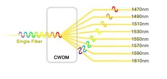
Coarse wavelength division multiplexing (CWDM) technology is developed to expand the capacity of a fiber optic network without requiring additional fiber. In a CWDM system, CWDM Mux/Demux (multiplexer/demultiplexer) is the most important component. Usually, a CWDM Mux/Demux is used to increase the current fiber cable capacity by transmitting multiple wavelengths, typically up to 18 separate signals over one fiber. This article may mainly describe what is Mux in networking and how to install your CWDM Mux/Demux system. Unless you are an experienced user, we recommend that you follow the detailed installation steps described in the rest of this article.
Introduction to CWDM MUX/DEMUX Module
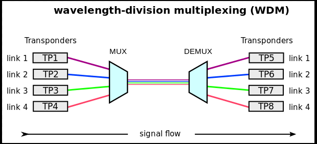
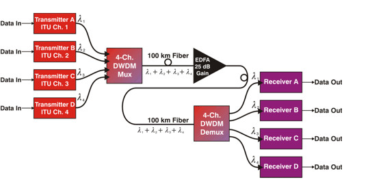
CWDM Mux/Demux module is a passive device, very reliable and simple to use. These devices are available with a variety of wavelength combinations, usually from 1270nm to 1610nm (20nm spacing). Based on different applications, a CWDM Mux/Demux module can be designed into different channels. A typical 4 channel Mux/Demux module will be used to multiplex four different wavelengths onto one fiber (shown in the picture below). This allows you to simultaneously transmit four different data over the same fiber. If you are using a CWDM multiplexer at the beginning of your network, you will use a CWDM demultiplexer at the opposite end to separate or demultiplex the wavelengths to allow them to be directed to the correct receivers. Usually, a CWDM Mux/Demux is a module that can be used as a multiplexer or demultiplexer at either end of the fiber cable span. However, it must still be used in pairs.
What IS MUX in Networking?
What is MUX in networking? A basic CWDM Mux/Demux system comprises a Local unit, the CWDM Mux/Demux module and a Remote unit. Usually, a Local or Remote unit refers to two different switches. In general, to install a CWDM Mux/Demux module, a chassis should be installed first to hold the module. Besides, to connect a CWDM Mux/Demux module to a switch, we should install CWDM SFP transceivers in the switch first. Then using the single mode patch cables to connect the transceivers to the CWDM Mux/Demux module. Therefore, when we want to build a CWDM Mux/Demux system, the components we need usually include rack-mount chassis, CWDM Mux/Demux module, CWDM SFP transceiver and single mode patch cables (shown in the table below).
| Part Name | Product Photo | Description |
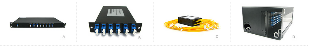
| Rack-mount Chassis |  |
Customized Empty Rack Chassis to hold 2/3/4/12 Pieces custom small size LGX Cassette |
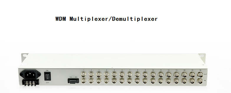
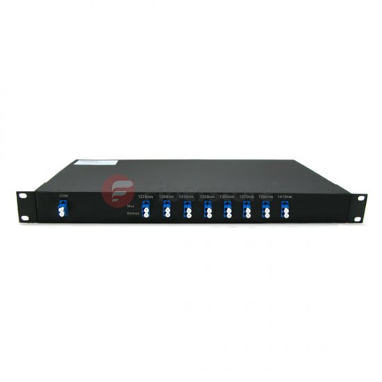
| CWDM Mux/Demux |  |
2/4/5/8/9/16/18 Channels CWDM MUX DEMUX 1270nm to 1610nm with Monitor Port |
| CWDM SFP Transceiver |  |
1.25Gbps CWDM SFP 1270nm to 1610nm 20/40/80/100/120km Transceiver |
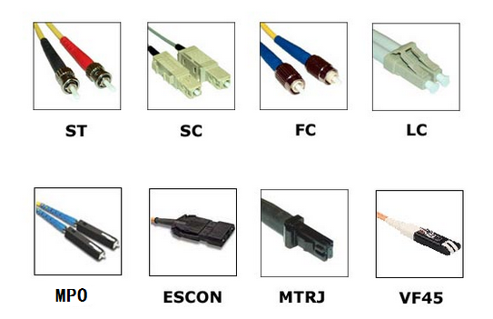
| Singlemode Fiber Cables |  |
LC to LC 9/125 Simplex/Duplex Single-mode Fiber Patch Cable |
How to Add CWDM MUX/DEMUX System to Your Network?
After knowing what is MUX in networking? Next, we’ll learn how to install a CWDM Mux/Demux system, there are four basic steps:
- Install the Rack-Mount Chassis
The CWDM rack-mount chassis can be mounted in a standard 19-inch cabinet or rack. When to attach the chassis to a standard 19-inch rack, ensure that you install the rack-mount chassis in the same rack or an adjacent rack to your system so that you can connect all the cables between your CWDM Mux/Demux modules and the CWDM SFP transceivers in your system.
- Install the CWDM Mux/Demux Modules
To insert a module, you should align the module with the chassis shelf (shown in the figure below) first and then gently push the module into the shelf cavity. Finally, tighten the captive screws.
- Connect the CWDM Mux/Demux to Switch
After inserting the CWDM SFP transceiver into the switch, then we should use the single mode patch cable to connect the transceiver to the CWDM Mux/Demux.
Please mind that CWDM Mux/Demux pairs must carry transceivers with the same wavelength. Because each transceiver will work only at the appropriate port and the data will always flow between devices with the same wavelengths. CWDM SFP transceivers with different wavelength may have a different color code. Use the CWDM SFP transceiver color codes shown in the picture below to help you connect the CWDM Mux/Demux to your system.
- Connect the CWDM MUX/DEMUX Pairs
Once you use a CWDM multiplexer on one end of your networks, you must use a demultiplexer on the other end of the networks. Therefore, the last step to complete CWDM Mux/Demux system is to connect the Mux/Demux pairs (or multiplexer and demultiplexer). For duplex Mux/Demux, a pair of single mode patch cables must be used. For simplex Mux/Demux, only one single mode patch cable is enough. After all done, your CWDM Mux/Demux system is then installed successfully.
Conclusion
What is MUX in networking? In summary, Mux/Demux system is a cost-effective solution which is easy to install. CWDM Mux/Demux, CWDM multiplexer only, and CWDM demultiplexer only are a flexible, low-cost solution that enables the expansion of existing fiber capacity and let operators make full of use of available fiber bandwidth in local loop and enterprise architectures. Fiberstore CWDM Mux/Demux is a universal device capable of multiplex multiple CWDM (1270~1610nm) up to 18 channels (2, 4, 5, 8, 9, 16, 18 channels are available) or optical signals into a fiber pair or single fiber. Together with our CWDM transceivers or the wavelength converters, the bandwidth of the fiber can be utilized in a cost-effective way.