How to Avoid Overheating in PoE Cabling?

Power over Ethernet (PoE) technology, which combines power and data transmission together over a single cable, has made great advances over the last decades. Applications for PoE have extended from the VoIP phone and security camera to IoT devices including medical devices, access control systems for intelligent buildings, etc. Every evolution in PoE technology has witnessed the transition to higher power level, however, the overheating issue along with higher power in PoE cabling becomes an essential issue. This post will discuss the heat rise with high power PoE as well as exploring solutions to avoid overheating problems.

Evolution of PoE Standards

As the PoE market continues to grow, PoE standards go through several generations of versions from the primary IEEE 802.3af standard to the latest IEEE 802.3bt standard to accommodate the market needs. In the following chart, we will take a closer look at the four PoE standard types.

Type 1Type 2Type 3Type 4
NamePoEPoE+PoE++, UPoEHigh-Power PoE
PoE StandardIEEE 802.3afIEEE 802.3atIEEE 802.3btIEEE 802.3bt
Max. Power per Port15.4 W30 W60 W100 W
Power to PD12.95 W25.5 W51 W71.3 W
Twisted Pair Used2-Pair2-Pair4-Pair4-Pair
Supported CablesCat5eCat5eCat5eCat5e
Typical ApplicationIP phoneVideo phoneMGMT deviceLED lighting

The PoE standard IEEE 802.3af, also called PoE type 1 is an early standard designed for the low power needed devices such as traditional IP phones and the security camera. Nevertheless, with the appliance of high power devices, 12.95W is not enough for their needs, which hence becomes a limitation of PoE. Later, the early standard was followed by the IEEE 802.3at which expanded the range of PoE applications such as video telephone and dual-band desktop access, and then came the latest IEEE 802.3bt standard. Along with the increased PoE power level, it causes a temperature rise within a PoE cable. Especially when the PoE power output reaches as high as 100 W, the heat rise of PoE cable will become more obvious.

Heat Rise—The Concern Emerging With High Power PoE

In the previous IEEE 802.3af and IEEE 802.3at PoE standards, the maximum power provided by PSE is 15.4W and 30W accordingly. It is not likely to overheat at this level of power unless under extreme ambient temperatures or cable bundles are too large. Two pairs of the four pairs in an Ethernet cable is enough to carry the current. However, as the power to the end devices is increasing, PoE cabling is bound to improve to deliver higher power. The effective means to improve the cable efficiency is to increase the number of wires carrying the power—Type 3 and type 4 PoE standard uses all four pairs to inject power rather than 2 pairs used in the early standards.

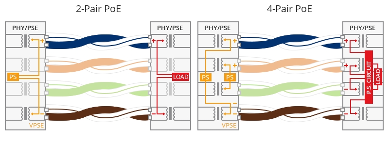
Figure 1: 2-pair PoE vs 4-pair PoE

The 4-pair PoE doubled the amount of available power, enabling PoE expanding to support higher-powered devices instead of being limited to the devices needing low power such as 15W or 30W. However, high power is not the only thing requiring attention in PoE cabling. Heat rise is another one. Manufacturers and technical consortiums have worked to evaluate the thermal impact of delivering 100 Watts of power over 4-pair PoE. Apparently the increasing power increases current flow, which significantly results in an increase in cable heating.

Why Is Heat Rise a Key Issue?

Why do we consider heat rise in PoE cabling so seriously? It is all because of the negative effects of heat rise on the link stability, and cabling lifespan.

Overheat in PoE cabling can result in an increase in insertion loss. To maintain the signal quality, administrators have to shorten the cable length to compensate for the loss in the link. Heat rise will lead to the premature aging of jacketing materials. If operated under the high-temperature circumstances for a long time, the outer jacket may get broken and impact the inner construction, breaking the balance of the twisted pair cable and causing the decline of electric performance. Furthermore, since the influence of heat rise in high power PoE is irresistible, careful evaluation before the PoE cabling deployment is required in the event of subsequent disposal. Better cabling cool will help to reap the benefit of excellent transmission performance.

Common Types of High Power PoE Applications

As has been mentioned in the front section, heat rise occurs with high power PoE cabling. Driven by the need for higher power all around the world, new PoE technology is expected to progress to enable new PoE markets and widen PoE’s scope to the existing markets requiring high power. Applications that take advantage of high power PoE technology include:

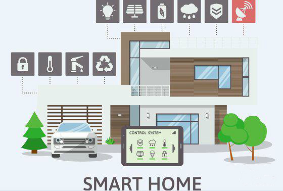
  • Intelligent buildings with enterprise IoT (connected LED lighting)
  • Safe cities (high definition pan-tilt-zoom security cameras)
  • Retail POS systems and digital signage
  • High-performance wireless access points
  • Kiosks
  • Small cells

Precautions to Minimize Heat Rise in PoE Cabling

Ultimately, the overheating problem can be attributed to the cable/conductor construction and specific installation situations. The following suggestion to minimize heat rise in PoE cabling will be listed from these aspects in an exhaustive way.

1. Use higher category cabling

In general, the higher the cable category is, the lower the heat will rise. According to the testing results from Leviton engineers, the higher category cabling correlated with lower amounts of temperatures after they tested several different category types of fiber cables. For new PoE installations, TIA suggests Cat6A for use.

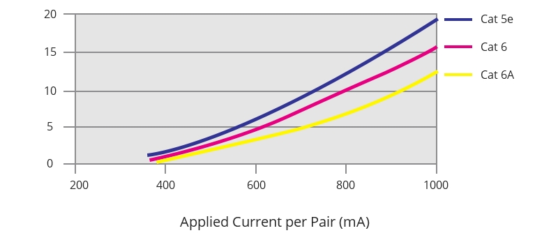
Figure 2: Current per category cable

2. Select cabling with a larger conductor (i.e., lower gauge number)

Heat rise can be the result of the conductor resistance in PoE applications. The larger the conductor is, the more it can reduce conductor resistance, the easier current flow it will allow for and the less heat it will generate.

3. Cable connectors should feature a solid metal body

Consider using connectors with an all-metal-body construction, instead of plastic. Compared with thermoplastic jacketing materials, mental has a higher conductivity and does better in heat dissipation.

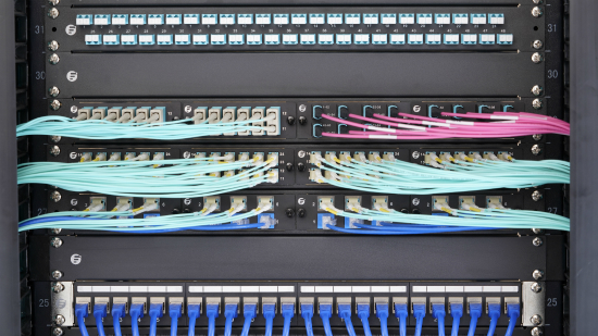
4. Choose cables with smaller bundle size

By measuring the temperature of a large cable bundle and the smaller bundles separated from the big one, TIA identified that the core of the large cable bundle experienced higher temperature in comparison to smaller bundles. TSB-184-A developed by the TIA subcommittee recommended leaving cables unbundled to facilitate better heat dissipation. If not possible, smaller bundle sizes are recommended.

5. Install shielded cabling

It has been affirmed that the existence of a metallic shield or foil helps dissipate heat. If the cable utilizes a foil shield around each pair, it will deliver better heat-dissipating qualities than the unshielded twisted pair cables. Therefore, S/FTP or F/UTP cables are more applicable than UTP cabling systems in PoE applications.

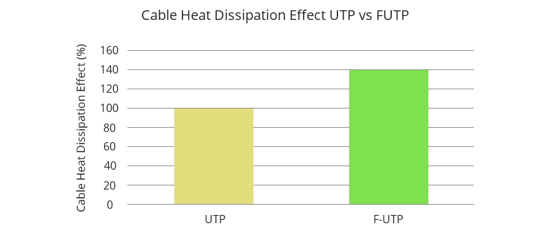
Figure 3: Cable heat dissipation effect UTP vs F/UTP

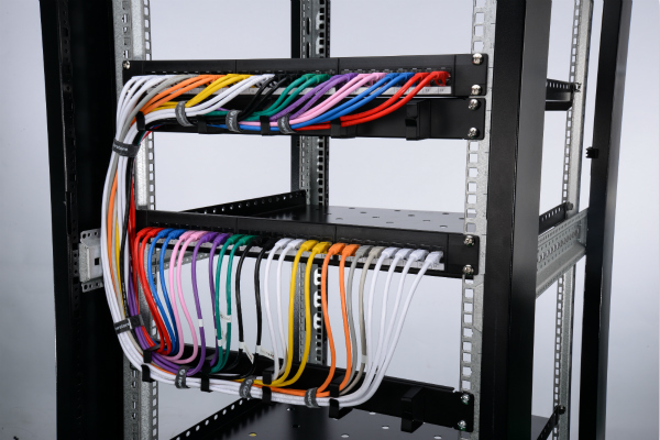
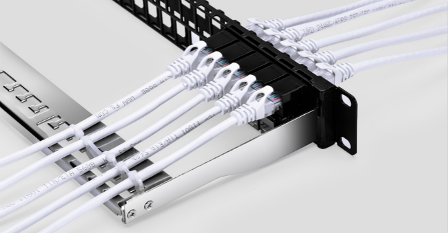
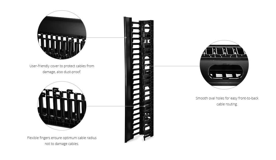
6. Plan your PoE cable management

Group your cables as loosely as possible instead of bundling all of them as a whole. Distribute your cable or cable bundles as dispersed as possible in an available area. High cable density will contribute to more heat within the cable or cable bundles. You are suggested to use cable management tools that allow for better airflow around cables and cable bundles.

Related Articles

How to Lower Cabling Temperature for PoE?

Powering PoE Switch From A PoE Switch: Is It Possible?

Article Source: How to Avoid Overheating in PoE Cabling?

What Is the Function of Patch Panel

As we know, patch panel is a passive device with a number of ports. It’s a cable management tool that most frequently used, typically in a data center. However, for some people, they are still confused about the function of patch panel, and post questions on forum such as what is the purpose of patch panel in networking, why not connect end device directly to switch? This article will help you find the answer.

How Patch Panel Works

Patch panels work in different ways due to the two types, fiber patch panel and copper patch panel. Usually, fiber patch panel is designed with ports both on the front and rear sides. Just insert the corresponding fiber cables into the ports, then you can achieve a neat cable management.

fiber patch panel

Figure 1: Fiber patch panel has ports on both sides.

Unlike the fiber patch panel, copper patch panel is divided into feed-through and punch down types. The feed-through panel contains RJ45 ports on two sides, which is convenient for users to plug the cables. And the punch down panel is equipped with Rj45 ports on the front side and punch down terminations and color coding on the rear side. Each set of punch down terminations corresponds to a port on the front side. So you have to terminate all cables into the patch panel first.

copper patch panel

Figure 2: The rear side of copper patch panel.

Main Function of Patch Panel

As a cable management tool, the primary benefit of using patch panel is the improved organization and easier management of your network. But how? As the figure 3 shows, a patch panel is usually installed within a server rack. And you may encounter many or even thousands of fiber optic cables and cable connection. Using a patch panel, you can label the patch panel, so that you know which end device or room the cable run goes to. This will be helpful when you need to make changes on the cables.

Also, we can see that all cables on the server rack have a bend radius (a term used to describe how sharply a cable can safely bend at any given point). If the fibers bent beyond the minimum bend diameters may lead to break, causing network failures. Therefore, using a patch panel, the cables bend radius will be reduced, which can enhance the cables’ long term reliability.

As described above, we have learned the main function of patch panel is to provide a robust, reliable management solution and protect the cables. It doesn’t have any electrical or logical function like the network switch or router. Patch panel is solely a physical connection, which means patch panel can’t replace a switch or a router.

function of patch panel

Figure 3: Cables are connected to the patch panel.

Where to Buy Patch Panel

FS.COM is the reputable source to buy patch panels. The following are some 1U patch panels I’d like to recommend to you.

1U Fiber Patch Panel

FS 1U fiber patch panels are designed with LC and SC ports. In order to meet different customers’ demands, FS has released 24 port patch panel and 48 port patch panel.

FS P/N
FHU-FPP48FLC10GMM
FHU-FPP48FSCSMF
FHU-FPP96FLCHSMF
Adapter Type
LC Duplex
SC Duplex
LC Duplex
Fiber Mode
OM3/OM4
OS2
OS2
Fiber Count
48 fibers
48 fibers
96 fibers
Insertion Loss
≤0.2dB
≤0.2dB
≤0.2dB
Return Loss
≥50dB
≥50dB
≥50dB

These 1U patch panels adopt the same material and design, but for different fibers connections. You can choose one according to your actual need.

1U Copper Patch Panel

FS provides Cat5e and Cat6 patch panels. Both are available in feed-through and punch down types. Here are the best-selling products.

FS P/N
C5EP-U24FT1U
C6P-U24FT1U
Cable Category
Cat5e
Cat6
Termination
Feed Through
Feed Through
Application
Unshielded
Unshielded
Port No.
24
24

The two products are used to connect unshielded copper cables. They share the same design. When you need to buy a copper patch panel, you should know what cables you want to connect, and this is very important.

Blank Keystone Patch Panel

If you need versatility of running different types of networking cable on a project, blank keystone patch panel is suitable for you. With a blank keystone patch panel, you can combine Ethernet cable, fiber cables through one patch panel. The following is a blank keystone patch panel from FS.COM. With no keystone jacks are pre-loaded into it, you can customize it according to your application.

keystone patch panel

Figure 4: Use blank keystone patch panel to make a mixed connection.

Conclusion

From the above, we know the main function of patch panel is to terminate all the cables, and provide a neat, reliable solution for cabling. When you want to buy one, please contact us via sales@fs.com.

Why Use A Patch Panel?

When we set up a network, we are accustomed to buying a patch panel as usual. And people always say they buy patch panels for cable management, as they are asked why use a patch panel. However, are there any other benefits of a patch panel? Yes, of course, here explains why use a patch panel in networking.

why use a patch panel

Figure 1: Patch panels in a rack for managing the fiber and copper cables.

Why Use A Patch Panel?

As shown in the picture above, patch panels are usually attached in the network racks. All the cables from the individual desktop, computer or printer go to the patch panel. Then the patch panel provides a protection and management for the cables, which contributes to ensure the cables’ performance in the whole network. This is the greatest benefit of using a patch panel. Whenever cables change direction, the bend of the cables is likely to change the electrical properties. If one cable bends too far, unfortunately, damages may occur inside where you can’t see it. So patch panels can help to protect the delicate cables.

Besides, using a patch panel improves working efficiency and workflow. How? For example, telecommunication and cable companies always use patch panels in strategic locations in their coverage areas. Therefore, the technicians can connect or disconnect services to the specific places without going to the actual locations just by managing the patch panels.

Finally, using a patch panel also improves the aesthetics of your work area. All cables are in place and accessible represent a well managed workstation, which also shows your professional quality.

Why Not Use A Switch Instead of Patch Panel?

When someone connects the cables, he may wonder why use a patch panel is a requirement and why they aren’t connected to network switches directly. The answer is that patch panel and switch play different roles in the cabling system. Patch panel acts just as a connector which will not make any influences on data transmission, but a network switch connects hardware within a network to enable them to access the Internet, share data etc. In a data center rack, there are many network switches with numbers of ports. Routing cables from one rack to another is a tough job. So you have to use patch panels to manage these cables.

Fiber and Copper Patch Panels Recommendation

Designed for specific cables like Cat5e, Cat6 copper cables and OS2, OM3 fiber cables, patch panels types are different.

Fiber Optic Patch Panel

This type of patch panel takes the simplex, duplex and quad model designs at FS.COM. There are 24 port patch panel and 48 port patch panel available for you to choose. All products are produced strictly in accordance with national standards. The following is a 24 port LC duplex fiber optic patch panel used to connect 48 OS2 single mode fibers. It uses the standardized jack that makes it easy to insert and remove fiber cables, so that to ensure the long-term and stable performance of the fiber cables.

fiber patch panel

Figure 2: 24 Port LC Duplex Fiber Patch Panel

Ethernet Patch Panel

FS.COM offers punch down and feed-through Ethernet patch panel. And the feed-through patch panel falls into unshielded and shielded types to wire the unshielded and shielded Ethernet cables. The following is a 24 port Cat6 unshielded feed-through patch panel. Design with SPCC and ABS plastics materials, the Ethernet patch panel is sturdy and durable that can work in the environment of -25°C to 70°C.

Ethernet patch panel

Figure 3: 24 Port Cat6 Unshielded Feed-Through Patch Panel

Blank Keystone Patch Panel

When you are unable to decide in advance which type of cables will be used to connect your hardware, you can use a blank keystone patch panel. The following is a 48 port blank keystone patch panel that provides flexibility in the type of jacks. As a result, you can make a mixed connection based on your actual demands.

blank keystone patch panelFigure 4: Cables connected on 48 port blank keystone patch panel.

Conclusion

What is the purpose of patch panel in networking, or why use a patch panel? I think now you have a good understanding. Today’s fast changing technology makes more and more electrical and electronic devices connected to each other, so don’t hesitate to use a patch panel to simplify the cabling.

Home Server Rack Setup: Making Your Home Intelligent

As we know, the server rack can organize numbers of network equipment into standard-sized rack, which greatly improves the working and management efficiency throughout the data center. Meanwhile, with the 5G IoT era approaching, more and more intelligent home appliances gradually enter our lives. People especially the IT men desire to use a centralized management to run these equipment. Of course, the best solution is the home server rack. But how much do you know about home server rack setup?

smart home

Figure 1: Intelligent Life is Coming.

What Can I Do With Home Server Rack?

Home server rack is the centralized point in your house where the wiring meets switches, routers etc. The most obvious thing that we can do with home server rack is protecting our hardware. Mounting them into the rack instead of putting them on or under a desk can avoid the risk of getting knocked over, having water or other liquids spilled on them. Besides, for the IT passionate and technology enthusiasts, they can use home server rack to build a small data center. With this, they can control and add whatever they please, like installing some game servers and email server in the meantime. So they can build their own services and have fun in running the services.

Considerations of Home Server Rack Installation Guide

As for the home server rack build, here are two aspects that must be considered so as to make sure everything goes smoothly.

Equipment numbers. Before you start the home server rack setup, you should take an inventory of your equipment such as switches, routers. Only know the specific numbers, we can determine the home server rack size. And here I suggest leaving some extra rack space, which is beneficial for cables go through the patch panel rack.

Rack location. We should determine the rack location based on convenience and available space. Because all the interior wiring like Cat5e, Cat6 for network and coax for television may join the home rack. Besides, an airy room is good for rack cooling. Thus choosing the right place in your building is critical.

How to Set Up a Server Rack?

Unlike the racks in the server room, there is no need to use a large server rack at home. So some people are fond of DIY. But I think to make a server rack may spend lots of time and energy. And most of them use the wood as the main material, which is not good for protecting the environment. Here I recommend the 12U server rack from FS.COM to you. Only cost 110 dollars, you can get a server rack that can be mounted on walls and placed on floors. It uses SPCC cold roll steel, which is more sturdy and durable than the wood ones. This equipment is specially designed with glass door to offer a better protection for your network devices, and cooling vents on the back to ensure airflow.

home server rack setup

Figure 2: Server Rack for Home

Now, we can place the 12U home server rack in the determined location. Then mount your various devices into the rack. If you have a budget for cable management tools, you can buy a keystone patch panel to manage your cables on racks. Thus, a home server rack setup has been established, you can manage your home network devices conveniently and enjoy the customized services.

Conclusion

Home server rack brings many advantages which may make your life a lot easier and intelligent. After all the work in home server rack setup, you can pride yourself in the creation and effort. So let’s design a home server rack, and start our smart life.

Single-Sided Vertical Cable Manager for 45U Server Rack

Server rack cable management is a finicky thing. In addition to a better organization of the fiber cables and power cords within racks, you have to run them orderly in vertical direction. Vertical cable manager is an important role for cable management, which will hold the cables snugly and safely to ensure the smooth data transmission. Here focus on single-sides vertical cable manager for 45U server rack.

Importance of Vertical Cable Management

The most significant usage of vertical cable management is cable bend radius protection. As we know, cable performance is determined by the physical properties of the cable, and therefore no matter when the cable changes direction, the fiber’s bend radius which has potential to impact cable performance will be generated at any point. To enhance the cables’ long-term reliability and reduce signal attenuation, vertical wire management tools allow convenient cable access with the acceptable bend radius.

Additionally, pulling behavior is inevitable during cable installation, so using a vertical cable management to define the vertical cable routing paths is of great importance, which will be the physical protection of the installed cables.

Overview of Single-sided Vertical Cable Manager for 45U Server Rack

Vertical cable organizer is similar to the horizontal cable category except for the orientation. Just as the name implies, single-sided vertical cable manager is perfect for keeping cables along a single rack or between two bayed racks. Here is a sample from FS.COM.

This 45U equipment is specifically designed to readily manage the challenges proposed by the data center’s high volume and density cabling system. It features contoured front door with easy-open knobs. Made of PVC material, the manager has plastic T-shaped cable fingers only on the front, which is comp

ly with RoHS standard. You can use it to support and manage large bundles of cables on the front rack. Besides, it has smooth oval holes that allow cables to come out wherever they are needed. Creatively, this 45U cable manager is composed by two 22.5U sections. Thus, you can utilize them to combine a 22.5U dual sided vertical cable manager.

vertical cable manager

Figure: Example of Single-sided Vertical Cable Manager

How to Use Single-sided Vertical Cable Manager

The following video gives a brief introduction of this FS vertical cable manager usage.

First, we should install the single-sided vertical cable manager. Adjust the vertical mounting rails and identify the mounting slots, then install finger directly onto the manager backbone. Don’t forget to insert the specially designed keyed brackets into the complete vertical cable manager.

Second, after that, we are ready to mount the manager on a server rack. Place the manager on one side of the rack, then use the screw to fix it. The installation is finished.

Last, manage the cables on the rack to go through the fingers, and the space is enough for both fiber and copper cables. Finally, remember to close the cover to protect the cables from dust.

Conclusion

Vertical cable manager is the perfect way for holding cables, which ensures everything is neatly and safely in place. FS.COM offers both vertical and horizontal cable management products to create the various cable pathways. Want to find a valuable cable management tool, please visit FS.COM.