
MDI/MDIX are types of Ethernet interface (both physical and electrical/optical) in a computer network used to carry transmission. They must be connected using the right twisted pair cable so that the transmission pair on one end is linked to the receiving pair on the other end, and vice versa. So what exactly are MDI vs MDIX ports? How do you choose the right Ethernet cabling when connecting MDI to MDIX or MDIX to MDIX? This post will address these issues and offer some insights into auto MDI/MDIX technology.
MDI vs MDIX: What Is the Difference?
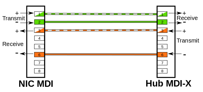
MDI (Medium dependent interface), also known as an uplink port, is an Ethernet port connection typically used on the NIC (Network Interface Card) or Integrated NIC port on a PC. The transmission signals on a NIC must go to receiving signals on the hub or network switch, so the latter devices have their transmission and receiving signals switched in a configuration known as MDIX – the “X” here represents “crossover”, indicating the reverse of input and output signals.

MDIX (Medium Dependent Interface Crossover) is an 8P8C port connection often found on a computer, router, hub, or network switch. Since MDIX is the crossover version of the MDI port, the pins 1 & 2 (transmitting) on an MDI device go to pins 1 & 2 (receiving) on an MDIX device via a straight through cable. Similarly, pins 3 & 6 (receiving) on an MDI device go to pins 3 & 6 (transmitting) on an MDIX device. In this case, the MDIX port eliminates the need for a crossover twisted pair cabling.
MDI vs MDIX: How to Choose the Right Cabling?
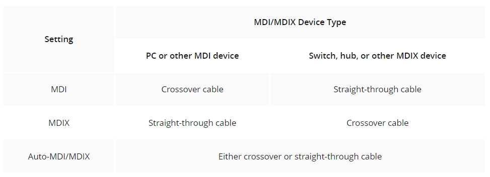
In general, end stations like PCs or workstations use an MDI interface, whereas hubs and network switches use MDIX interfaces. On other network devices like routers, multiple MDIX ports and a single MDI port often co-exist. The MDI port on the router is designed to connect a cable modem. Both ports are labeled MDI or MDIX to help you choose the right type of cable. As a rule, MDI ports connect to MDIX ports via straight-through twisted pair cabling. As for MDI-to-MDI or MDIX-to-MDIX connections, crossover twisted pair cables are deployed. In some cases, network hubs or switches are built with an MDI port (often switchable) in order to connect to other hubs or switches without a crossover Ethernet cable.
What About Ethernet Auto-MDI/MDIX?
As aforementioned, an Ethernet crossover cable is adopted to connect two ports of the same configuration (i.e. MDI-to-MDI or MDIX-to-MDIX). However, it may generate some confusion and inconveniences when deploying two different kinds of Ethernet cables. The auto-MDI/MDIX technology is developed to fix this problem: It automatically switches between MDI and MDIX as required. Auto MDI/MDIX ports on newer device interfaces detect if the connection requires a crossover, then automatically choose the MDI or MDIX configuration to properly match the other end of the link. In this case, it doesn’t matter if you using straight through or crossover cables. The chart below shows cable types for MDI/MDIX and auto-MDIX.
FS.com Gigabit PoE Switch With Auto MDI/MDIX
The latest routers, hubs and switches (including some 10/100, and all 1GB or 10GB Ethernet switch) use auto MDI/MDIX to automatically switch to the proper configuration once a cable is connected. FS.com 48 port switch S1600-48T4S is one of them. This Gigabit PoE+ managed switch comes with 48×10/100/1000Base-T RJ45 Ethernet ports and 4x 10G SFP+ slots, offering up to 180Gbps switching capacity, enterprise-class features and superior network security. The built-in auto-MDI/MDIX provides fast plug-and-play setup and eliminates the need for a crossover cable. It can also detect the link speed of the attached device and makes adjustments according to the compatibility and performance requirements, enabling the switch to be backwards compatible with legacy network devices.

Conclusion
To sum it up, MDI is an Ethernet port on end stations like PCs and workstations, whereas MDIX on hubs and network switches is the crossover version of MDI. You should employ straight through Ethernet cable for an MDI-to-MDIX connection and crossover cable for either MDI-to-MDI or MDIX-to-MDIX configuration. The auto MDI/MDIX connection address the MDI vs MDIX issues by automatically switching between MDI and MDIX, so you can opt for the cable types that suit your needs. If you still have problems regarding MDI/MDIX and auto MDI/MDIX technology, feel free to contact us at sales@fs.com.
Related Article:
8 Port PoE Switch Recommendations
What Is PoE and Power Over Ethernet Switch?
Article Source: MDI vs MDIX And Auto MDI/MDIX Basics


