How FS 400G MTP/MPO Cables Enable Efficient Connectivity

400G

The demand for 400G transmission rates by major data centers and telecom carrier continues to grow and cabling solutions are constantly being updated. In order to achieve 400G data rates and save cabling costs, breakthroughs, higher connection density, and simplified network design approaches must be considered, so 400G MTP/MPO cables are becoming more and more common. FS offers MTP/MPO cabling solutions to meet the needs of high-performance 400G networks. This article will describe specific cabling application scenarios.

A Glance at FS 400G MTP/MPO Cables and Transceivers

MTP/MPO cables with multi-core connector are used for optical transceiver connection. There are 4 different types of application scenarios for 400G MTP/MPO cables.

Common MTP/MPO patch cables include 8-fiber, 12-core, and 16-core. 8-core or 12-core MTP/MPO single-mode fiber patch cable is usually used to complete the direct connection of two 400G-DR4 optical transceivers. 16-core MTP/MPO fiber patch cable can be used to connect 400G-SR8 optical transceivers to 200G QSFP56 SR4 optical transceivers, and can also be used to connect 400G-8x50G to 400G-4x100G transceivers. The 8-core MTP to 4-core LC duplex fiber patch cable is used to connect the 400G-DR4 optical transceiver with a 100G-DR optical transceiver.
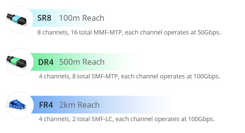
SR8-vs-DR4-vs-DR8.jpg

Figure 1: SR8-vs-DR4-vs-DR8

FS 400G MTP/MPO Cabling Solutions for Typical 400G Network Applications

As the network upgrades and data centers migrate to 400G rates, how to transition from existing 50G/100G/200G devices to 400G, here are FS MTP/MPO cabling solutions.

400G-400G Direct Connection

500m span with 8-fiber/12-fiber MTP/MPO cable

400G short and medium distance direct connection usually consists of 8-core/12-core MTP patch cable with 400G-DR4 OSFP/QSFP-DD modules. The term “DR4″—”DR” stands for 500m reach using single-mode fiber and “4” implies there are 4 x 100 Gbps optical channels. Since one optical channel requires two fibers, an 8-fiber or a 12-core MTP/MPO cable can be used for the 400G-DR4 module to achieve direct connection. In the 8-fiber MTP cabling, the fiber utilization is 100%, while in the 12-core MTP cabling, four fibers remain unused. Take 400G QSFP-DD module as an example, the following picture is presenting the MTP cabling for 400G DR4 direct connection.

400G-400G Direct Connection Scenario 1.jpg

Figure 2: 400G-400G Direct Connection Scenario 1

PRODUCTSDESCRIPTION
400G DR4 QSFP-DDGeneric Compatible 400G DR4 QSFP-DD PAM4 1310nm 500m DOM Transceiver Module
MTP®-12 (Female) 12 Fibers OS2 Single ModeOS2 Single Mode Elite Trunk Cable, 12 Fibers, Type B, Plenum (OFNP)

100m span with 16-fiber MTP/MPO cable

The 400G-SR8 transceivers require the use of a 16-core MTP cable. The term “SR8” – “SR” stands for a distance of 100 meters using multimode fiber, and “8” implies there exist 8 optical channels with each operating at 50Gbps. In this direct connection, the 16-core MTP cable has 100% fiber utilization. The primary adopters of these 400G-SR8 fiber transceivers are expected to be certain hyperscale cloud service providers in North America and China.

400G-400G Direct Connection Scenario 2.jpg

Figure 3: 400G-400G Direct Connection Scenario 2

PRODUCTSDESCRIPTION
400GBASE-SR8 QSFP-DDGeneric Compatible 400GBASE-SR8 QSFP-DD PAM4 850nm 100m DOM Transceiver Module
MTP®-16 APC (Female) OM4 CableOM4 Multimode Elite Trunk Cable, 16 Fibers, Plenum (OFNP), Magenta, 850/1300nm

400G-2x200G Direct Connection

100m span with 16-fiber MTP conversion cable

In the backbone and some more complex metropolitan area networks, the dual-carrier technology (2x200G) will be adopted to compress the channel spacing compared to a single-carrier 400G technology. Extending the transmission distance and improving the spectral efficiency, 400G-2x200G direct connection can help to deploy 400G backbone networks with minimum bandwidth resources.

In this case, 16-core MTP conversion cables terminated with MTP/MPO connectors on both ends are needed. With this type of cable, one 400G OFSP/QSFP-DD module and two 200G QSFP56 modules can be directly connected.
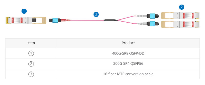
400G-2x200G Direct Connection Scenario.jpg

Figure 4: 400G-2x200G Direct Connection Scenario 3

PRODUCTSDESCRIPTION
400GBASE-SR8 QSFP-DDGeneric Compatible 400GBASE-SR8 QSFP-DD PAM4 850nm 100m DOM Transceiver Module
200GBASE-SR4 QSFP56FS for Mellanox MMA1T00-VS Compatible 200GBASE-SR4 QSFP56 850nm 100m DOM Transceiver Module
MTP®-16 APC (Female) OM4 CableOM4 Multimode Elite Trunk Cable, 16 Fibers, Plenum (OFNP), Magenta, 850/1300nm

400G-4x100G Direct Connection

500m span with 8-fiber MTP/MPO trunk cable and 4-LC duplex patch cable

In the 400G to 4x100G migration scenario, an 8-core MTP-LC cassette that packaged in the fiber rackmount enclosure is adopted to realize the transmission from MTP to LC, and then an 8-core MTP/MPO trunk and 4-LC duplex patch cables are used to connect at both ports.

The 400G-4x100G architecture uses four optical modules with 100Gbps wavelengths. However, the current 100G technology is based on a 4x25G design and unable to scale to 400G. 100Gbps per channel can be achieved using PAM4 technology and then aggregated to achieve an overall 400Gbps speed with 4x100G. MTP/MPO cables allow splitting 400G bandwidth into multiple 100G or 40G data streams.

400G-4x100G Direct Connection Scenario.jpg

Figure 5: 400G-4x100G Direct Connection Scenario 4

PRODUCTSDESCRIPTION
400G DR4 QSFP-DDGeneric Compatible 400G DR4 QSFP-DD PAM4 1310nm 500m DOM Transceiver Module
100GBASE-DR QSFP28 Single LambdaGeneric Compatible 100GBASE-DR QSFP28 Single Lambda 1310nm 500m DOM Transceiver Module
MTP® Female to 4 LC UPC Duplex 8 FibersMTP Type B Plenum (OFNP) OS2 9/125 Single Mode Elite Breakout Cable 1310/1550nm
FHD MTP®-8 Cassette to 4x LC Duplex (Blue)8 Fibers OS2 Single Mode, Universal Polarity, MTP® to 4x LC Duplex (Blue), 0.35dB max
Customized 8-144 Fibers MTP®-12OS2 Single Mode Elite Breakout Cable
FHD 144 Fibers (LC) EnclosureFHD High Density 1U Rack Mount Enclosure Unloaded, Tool-less Removable Top Cover, Holds up to 4x FHD Cassettes or Panels

400G-8x50G Direct Connection

500m span with 16-fiber MTP conversion cable and LC duplex patch cable

The rapid growth of 400G has contributed in part to the less popular 50G market, and MTP/MPO cables provide the technology to scale 50GbE to accommodate 400G (8x50G) network. For this scenario example, the MTP cassette is in the middle to connect the 16-core MTP conversion cable and the LC duplex patch cords together to realize the 400G-8x50G direct connection. Eight 50G lanes can support the optical link of 40Gbps aggregation via PAN modulation.

400G-8x50G Direct Connection Scenario.jpg

Figure 6: 400G-8x50G Direct Connection Scenario 5

PRODUCTSDESCRIPTION
400G DR4 QSFP-DDGeneric Compatible 400G DR4 QSFP-DD PAM4 1310nm 500m DOM Transceiver Module
MTP®-16 APC (Female) OM4 CableOM4 Multimode Elite Trunk Cable, 16 Fibers, Plenum (OFNP), Magenta, 850/1300nm
FHD MTP®-24 Cassette to 12x LC Duplex (Aqua)24 Fibers OM4 Multimode, Type A, MTP® to 12x LC Duplex (Aqua), 0.35dB max
MTP®-16 APC (Female) to 8 LC UPC Duplex CableOM4 Multimode Elite Breakout Cable, 16 Fibers, Plenum (OFNP), Magenta,850/1300nm
FHD 144 Fibers (LC) EnclosureFHD High Density 1U Rack Mount Enclosure Unloaded, Tool-less Removable Top Cover, Holds up to 4x FHD Cassettes or Panels

Scaling to FS 400G MTP/MPO Cabling System for 400G Networks

400G is increasingly becoming ubiquitous in many high-performance and high-density networking environments. 400G MTP/MPO cables have been widely used as cabling solutions for 400G network transmission rates due to their unique cabling simplicity and cost reduction benefits. FS offers a wide range of related 400G MTP/MPO cabling products and solutions to smoothly achieve high-speed data transmission.

Original Source: How FS 400G MTP/MPO Cables Enable Efficient Connectivity

Shocked! Most Cat5e/Cat6 Ethernet Cables Fail to Meet the Rated Specification

Recently, a number of reports indicate that most open-market patch cords, such as Cat5e/Cat6 Ethernet cables, do not meet the standard specifications. In fact, the result comes as no surprise. There are two versions of the specifications, TIA and ISO (ISO is more stricter than TIA), but neither of these standards involves enforcement organization or licensing. Vendors get away with inferior Ethernet cable because the average consumer is the least able to buy the equipment worth $10,000 to check the purchase against specifications.

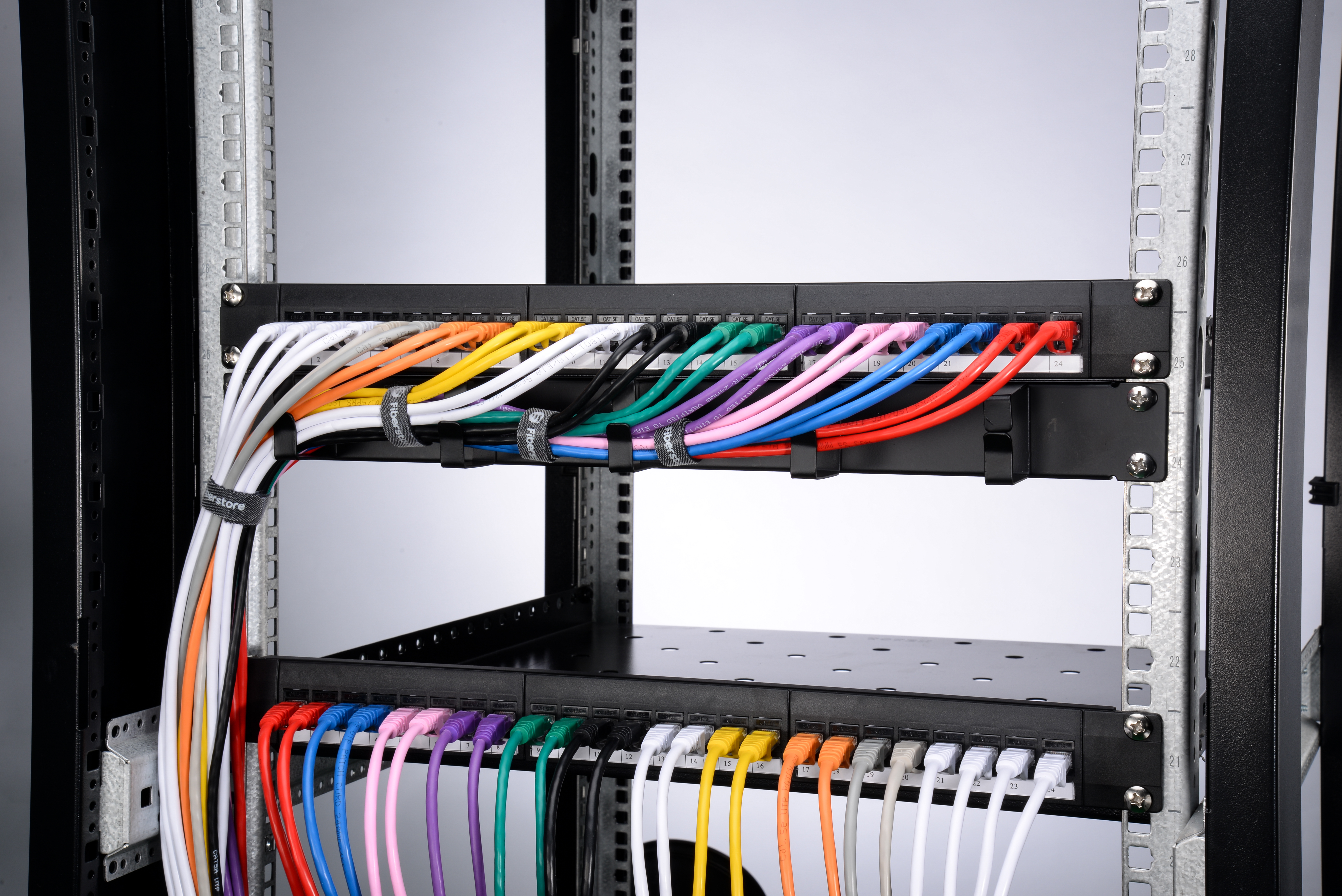
alt Cat5e/Cat6 Ethernet cable

Why Cat5e/Cat6 Ethernet Cable Do Not Meet the Standard?

The cat5e patch cable we used is designed to meet performance specifications up to 100 MHz (as specified in TIA-568-C.2), enabling it to handle common 100Base-T and 1000Base-T wired networks. The cable cat6 has higher performance confirmed to 250 MHz; enabling it to handle 10GbE wired networks. However, many vendors do not take specification compliance seriously because the transmission rate of the standard Ethernet cable and inferior Ethernet cable cannot be judged easily by non-professionals, but only by cable test devices. So some vendors manufacture Ethernet cables to very lax quality standards, which leads the good and the bad patch cords are intermingled on the market.

What Are the Consequences of Cat5e/Cat6 Not Meeting the Standard?

Assuming that your network switches are all set up correctly, the bad links will slow down by themselves, but the rest of the network will run at full speed. Otherwise, the switches will turn down the speed of every link due to one bad link, and the whole node slows down. This will affect your network transmission rate and data transmission. What’s worse, inferior Ethernet cables sooner or later will cause poor network performance and could even damage active equipment. Installing counterfeit cables is a risk that eventually will have an expensive cost of maintenance.

How to Avoid Buying Inferior Cat5e/Cat6 Ethernet Cables?

So if you want to avoid buying counterfeit cables, you have to make sure the following four points.

alt Cat5e/Cat6 Ethernet Cable

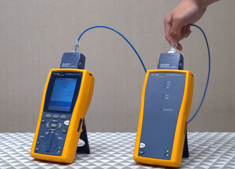
Use Ethernet Cable Passed the Fluke Test

The Fluke test is considered as the most authoritative criteria for telling the quality of an Ethernet cable. This test includes patch cord testing and channel testing for Ethernet patch cables, and permanent link testing for bulk network cables. For Ethernet patch cables, the channel standard is not the applicable specification and is much easier to pass. Therefore cables passing the patch cord testing have higher performance.

Use Ethernet Cable With Oxygen-Free Copper Wire

The conductor material of copper-clad-steel or copper-clad-aluminum is a classic method manufacturer use in order to save money, which is easy to cause high attenuation and poorly signal. It is the purity of copper that determines the Ethernet cable quality. The purer the copper wire is, the less signal loss you will suffer. The purity of copper in descending order is oxygen-free copper > pure copper > bare copper > copper clad aluminum > copper-clad-steel. So you’d better choose oxygen-free copper wires. To learn more about choosing the best network cable wire, please read Network Cable Wire: Oxygen-Free Copper VS Pure Copper VS Copper Clad Aluminum VS Aluminum

Use Ethernet Cable With Fire-Proof Cable Jacket

There are two types of Ethernet cable jacket, non-flame retardant, and flame retardant jacket. Maybe not every application requires a cable to have a flame retardant jacket, but when needed, it is critical for cables to have a flame retardant jacket for safety concern. Normally Ethernet cables with PVC CM and CMP jacket are commonly used in patch cabling environment. However, some manufacturers replace CM and CMP flammability rating with inferior non-fireproof jacket material. That’s one point you would not want to miss.

Use Ethernet Cable Made By Reliable Manufacturers

Last but not least, instead of buying the cable test devices, you need to select reliable sellers that can provide the Fluke test reports and product details of above. Buying cables from a reliable manufacturer is directly related to your cable performance.

Conclusion

Choosing reliable manufacture is half the success of choosing a qualified Ethernet cable. Every Ethernet patch cables FS sells comes with its individual Fluke test report, showing that it meets the rated specification. If it doesn’t, FS won’t sell it. We manufacture the patch cable with top-quality oxygen-free copper and environment-friendly CM flame retardant jacket, and we certification-test every cable to ensure the performance. You’re welcomed to visit www.fs.com to find what you need.

Related Articles:
How to Choose and Buy the Best Ethernet Cables
Quick View of Ethernet Cables Cat5, Cat5e And Cat6
Solid or Stranded Conductor Cable, Which to Choose?

Network Cable Wire: Oxygen-Free Copper VS Pure Copper VS Copper Clad Aluminum VS Aluminum

There are many Ethernet network cable wires used for data center applications such as Cat5e, Cat6, Cat6a, and Cat7 cables. The conductor metals adopted by those network patch cables vary in different kinds such as oxygen-free copper wire, pure copper wire, copper clad aluminum wire, and aluminum wire. This article discusses the above network cable wire and compares the differences.

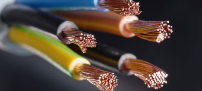
alt Network Cable Wire: Oxygen-Free Copper VS Pure Copper VS Copper Clad Aluminum VS Aluminum

What Is Oxygen-Free Copper Wire?

An oxygen-free copper wire is the highest conductivity copper cable wire that is refined to reduce the amount of oxygen to less than 0.003%, the total impurity content to less than 0.05%, and the purity of copper to more than 99.95%. Thereby, improving the conductivity and oxidation resistance.

What Is Pure Copper Wire?

The pure copper wire has a slightly lower copper content than that of oxygen-free copper wire, which is around 99.5% to 99.95%. The other impurities are some metals such as iron and oxygen. The pure copper wire has excellent conductivity, thermal conductivity, plasticity, and is easy to be pressed.

What Is Copper Clad Aluminum Wire?

The copper clad aluminum wire is an electric conductor composed of an inner aluminum core and an outer copper cladding. Since it contains aluminum, it is significantly lighter and weaker than pure copper wire or oxygen-free copper wire, but stronger than pure aluminum wire. Copper clad aluminum wire is not compliant with UL and TIA standards, both of which require solid or stranded copper wires, but it’s a cheap alternative for category twisted-pair communication cables.

What Is Aluminum Wire?

An aluminum wire is made of pure aluminum. Due to the lightweight nature of aluminum, aluminum wire is quite malleable. However, when compared with copper wire, it has lower electrical and mechanical properties, which is a relatively poor electrical conductor.

Aluminum VS Copper Wire: Which Is the Better Network Cable Wire?

Despite being the best material, copper is a little expensive than aluminum. Thus, people prefer to use aluminum to save money without compromising quality. However, when the aluminum wire warms, it expands, and when it cools, it shrinks. With each gradual warm-cool cycle, the tightness of the wiring decreases, resulting in sparks, even fires. Aluminum wire will also corrode when it encounters certain metal compounds, which increase the resistance to the connection. Thus, aluminum wire requires higher maintenance than copper wire. In contrast, copper has one of the highest electrical conductivity rates among metals. Copper has high tensile strength so it can withstand extreme stress and is more durable. Due to its high elasticity, high durability, low maintenance, and high performance, it is a more stable material than aluminum. So a good manufacturer will use a great deal more copper in the wire to ensure the performance.

Conclusion

Now we know that copper wire outweighs aluminum wire when used in wired networks. The higher the copper content of the network cable wire, the better the conductivity and transmission capacity. However, most of the network cables sold on the market are pure copper wires or copper clad aluminum wires. FS provides oxygen-free copper wires, which outperforms among the peers. These oxygen-free copper wires are 100% pass the Fluke Channel Test with PVC CM jacket material, making them the best choice for you in terms of price and quality. If you’re interested, please visit www.fs.com.

Related Articles:
How to Choose and Buy the Best Ethernet Cable
Quick View of Ethernet Cables Cat5, Cat5e And Cat6
Solid or Stranded Conductor Cable, Which to Choose?

SFP28 Cable: Why Choose It?

Over the years, our demand for communication bandwidth requirements has increased dramatically. Communication service providers, public or private data centers require higher speed and bandwidth connections. At this time, a new Ethernet connectivity standard, 25 Gigabit Ethernet was proposed. The release of the 25G Ethernet standard has provided a new path for data center server connections. This article will discuss 25G SFP28 cable and why you should choose it.

What Is SFP28 Cable?

SFP28 cable, also known as SFP28 DAC (Direct Attach Copper ) Twinax cable or SFP28 AOC (Active Optical Cable) cable, is a form of a high-speed cable with SFP28 connector on either end. It features with lower power consumption and lower interconnection loss, which makes it suitable for TOR (Top-of Rack) switch to server connectivity.

altSFP28 Cable: Why Choose It?

How Many Types of SFP28 Cable?

The SFP28 cable can be classified to 25G SFP28 DAC cable and 25G SFP28 AOC cable. And they are all present to be the most economical choice for TOR 25gbe switch connections. Here we will explain each cable one by one.

25G SFP28 DAC Cable

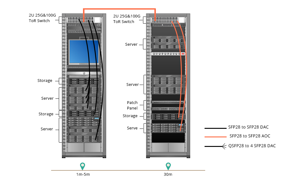
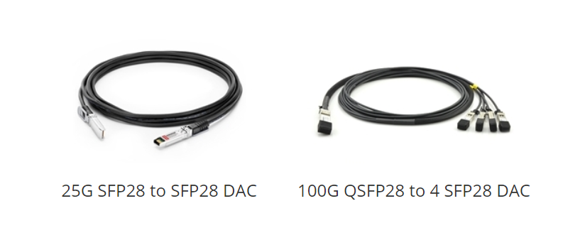
SFP28 DAC is a form of a shielded high-speed SFP28 cable with pluggable transceivers on either end. Generally, there are two popular types of SFP28 DACs on the market, 25G SFP28 to SFP28 DAC and 100G QSFP28 to 4 SFP28 DAC. 25G SFP28 to SFP28 DAC cable is usually a passive cable on the market. It has no signal amplification in the cable assembly, so it’s often used for ultra short reach (≤5m). 100G QSFP28 to 4 SFP28 DAC uses breakout cables connect to a 100G QSFP28 port switch on one end and four 25G SFP28 ports switch on the other end, making it a highly cost-effective way to achieve short distance. Normally 25G SFP28 DAC can be used to the interconnection of switches, routers, storage devices, and servers.

altSFP28 Cable: Why Choose It?

25G SFP28 AOC Cable

SFP28 AOC has a similar appearance as SFP28 copper cable, but its transmission method and application environment are not the same. There are two types of SFP28 AOCs on the market, 25G SFP28 to SFP28 AOC and 100G QSFP28 to QSFP28 AOC. SFP28 AOC uses electrical-to-optical conversion on the cable ends to improve speed and distance performance of the cable. Compared to the SFP28 copper cable, SFP28 AOC usually has a longer transmission distance and better transmission performance. Compared with the optical transceiver module, it does not have the problem of the interface being contaminated, which greatly improves the stability and reliability of the system and reduces the management costs of the server room. SFP28 AOC cable is the ideal cable for the connection between rack and rack on a data center, which is generally optimized for lengths.

altSFP28 Cable: Why Choose It?

Benefits of 25G SFP28 Cable Connections

The development of 25G SFP28 cable connections has provided a wide range of benefits, especially in a web-scale data center environment.
Primarily, SFP28 cable is suitable for short-distance cabling of a network solution, which has a scientific layout design to save space with more reasonable length. It can efficiently utilize data and switch port density.
Moreover, SFP28 cable provides an extremely efficient increase in speed to the server to TOR, especially when using the DAC assembly. It also simplifies the development of interoperability specifications and systems due to the fact that it is backward compatible and gives an easier upgrade path from an existing 10G TOR server configuration.
Furthermore, using 25G SFP28 cables for TOR servers are more economical. This is because SFP28 cable can provide higher port densities, fewer TOR switches and cables are needed. It allows a more cost-effective alternative TOR server connection that connects via point-to-point links. It also enables EOR (End of Row) or MOR (Middle of Row) by using structured cabling.

The Future of SFP28 Cable Connections

25G SFP28 cable solutions feature a lower power consumption and smaller footprint requirement for data centers. Due to the benefits provided by 25G SFP28 cable assembly, it is expected that it will be popular in the years to come. It is believed that the dominant next-generation server connection is towards the 25Gbps speed in the server. And in the near future, more devices will use the 25G SFP28 DAC or AOC cable assembly solutions. FS.COM offers a variety of SFP28 DAC/AOC options, such as SFP-H25G-CU3M, SFP28-25G-AOC1M and so on. You can have a visit and choose the products you need.

Related Articles:
Taking an In-depth Look at 25G SFP28
Decoding 100G QSFP28 Transceiver

Necessary Tips for Fiber Optic Cable Installation

FTTH, the concept that has been hotly debated by people in recent years, drives the demand for fiber optic cables and its related products. However, fiber optic cable is fragile and hard to splice, which is worthy of consideration before installation. To make good use of fiber optic cable, well-organized fiber optic cable installation is a necessity.

Fiber Optic Cable Introduction

Fiber optic cable is a technology that uses small threads made of glass or plastic (fibers) to transmit data. However cheap and light it is, the material brings a troubling problem in fiber optic cable installation. It is an assembly similar to an electrical cable while the former one carries light and the latter carries electricity. Normally, fiber optic cable comes in two types, namely, single mode fiber (SMF) and multimode fiber (MMF). Single mode fiber is suitable for long distance data transmission while multimode optical fiber is used in short distance transmission such as computer network linking. Regardless of fiber optic cable types you use, it is necessary to maintain a good fiber optic cable installation.

fiber optic cable installation

Benefits for Good Fiber Optic Cable Installation

Good Working Performance

Good fiber cable installation ensures the highly effective and smooth working of the fiber optic cables. The cables can not only conduct high-speed signal transmission, but also carry more bandwidth. Moreover, if operate inside a large building or fiber optic home wiring, the signal will be strong everywhere in each room, for the fiber optic cables can carry strong signal strength over long distances.

Less Maintenance and Repairs

There’s nothing more annoying than a frequently breaking down cable system. A good fiber optic cable installation can spare you a lot of energy in the future maintenance and repairs, preventing endless frustrations. As for making a good structural installation plan, there are many things to consider. The next part will shed light on fiber optic cable installation guidelines.

Guidelines for Fiber Optic Cable Installation

Fiber cable installation can be categorized into different types, namely aerial fiber installation, direct burial installation, underground duct installation and household fiber cable installation. Regardless of the cabling condition, bear in mind the following guidelines.

Start with proper planning so as to avoid mistakes and problems. Inspect the route before cable installation, detect the possible problems and get the solutions. Decide the number of cabling and connections needed. Moreover, we’d better consider planning ahead for installing additional cabinets, servers and network components.

fiber cable installation

Test every fiber optic cable before and after the installation. For, example, use visual fault locator to find breaks in fiber cable. Make timely replacement or repairs to guarantee the normal installation process.

Do not bend or kink fiber cables. Never exceed the cable bend radius of the fiber patch cord. These will harm the fibers. Use necessary tools to maintain a minimum bend radius of the installed fiber optic cable. Another way is to use bend insensitive fiber cables. Some vendors like FS provides BIF fiber patch cord of 10mm maximum bend radius, which is more flexible in cabling.

Do not mix or match varied core sizes. Here recommends cable ties to bind the same type of cables together in case of confusion. Cable labels also can be used to mark different cables for easy identification.

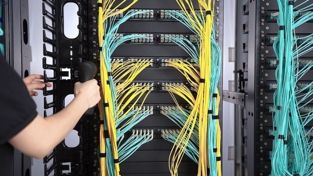
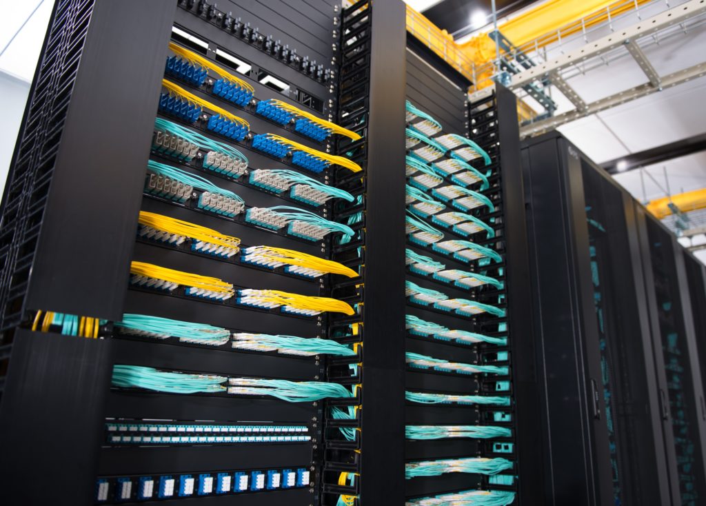
Use proper tools and techniques. Tools such as fiber patch panel, cable management panel can keep a well-organized cabling. And fiber enclosures can protect cables from external damage and are dust-proof. Fiber raceway can be installed overhead to route and support the cables. FS highly trained and skilled experts specialized in data cabling installation and fiber optic cabling installation are equipped with the necessary tools to create both permanent and temporary joints between fibers according to fiber optic cable installation standards.

Conclusion

It is undeniable that fiber optic cable is worthwhile trying. However, do not follow suit to buy what you actually don’t need. Make clear of its advantage and figure out the fiber optic cable installation. First and foremost, read through this article.

Related Articles:What Is Fiber Optic Cable and How Does It Work?
Bend Radius—How It Can Impact Your Cable Performance?