Different Ports on WDM Mux/Demux

In the WDM (wavelength-division multiplexing) system, CWDM (coarse wavelength-division multiplexing) and DWDM (dense wavelength-division multiplexing) Mux/Demux (multiplexer/demultiplexer) modules are often deployed to join multiple wavelengths onto a single fiber. Multiplexer is for combining signals together, while demultiplexer is for splitting signals apart. On a WDM Mux/Demux, there are many kinds of ports for different applications. This article will discuss the functions of these ports on WDM Mux/Demux.
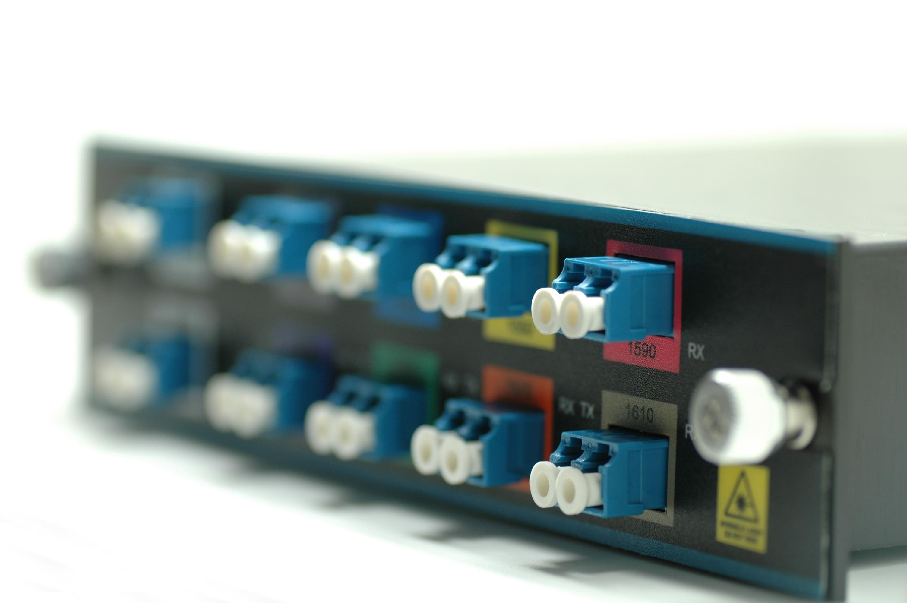
WDM Mux/Demux

Necessary Ports on WDM Mux/Demux

Channel port and line port are the necessary ports to support the basic function of WDM Mux/Demux to join or split signals in the data network.

Channel Port

A WDM Mux/Demux usually has several channel ports on different wavelengths. Each channel port works for a specific wavelength. Since there are 18 wavelengths of CWDM ranging from 1270 nm to 1610 nm with a 20nm interval, the number of channel ports on CWDM Mux/Demux also ranges from 2 to 18. DWDM has a more dense wavelength spacing of 0.8 nm (100 GHz) or 0.4 nm (50 GHz) ranging from S-Band to L-Band around 1490 nm to 1610 nm. The number of DWDM Mux/Demux channel ports is about 4 to 96 for high-density networks.

Line Port

Each WDM Mux/Demux will have a line port connecting to the network backbone. Combined channels are transmitted or received at the line port. In addition, line port can be divided into dual-fiber and single-fiber types. Dual-fiber line port is used for bidirectional transmission, therefore the transmit and receive port in each duplex channel must support the same wavelength. However, single-fiber line port only supports one direction data flow, thus the transmit and receive port of duplex channel will support different wavelengths. The wavelengths’ order of single-fiber WDM MUX/DEMUX should be reversed at both sides of the network.

Special Ports on WDM Mux/Demux

Apart from the necessary ports, some special ports can also be found on WDM Mux/Demux for particular needs.

1310nm Port and 1550nm Port

1310nm and 1550nm ports are certain wavelength ports. Since a lot of optical transceivers use these two wavelengths for long-haul network, adding these two ports when the device does not include these wavelengths is very important. CWDM Mux/Demux can add either type of wavelength ports, but the wavelengths which are 0 to 40 nm higher or lower than 1310 nm or 1550 nm cannot be added to the device. However, DWDM Mux/Demux can only add 1310nm port.

Expansion Port

Expansion port can be added on both CWDM and DWDM Mux/Demux modules. This is a special port to increase the number of available channels carried in the network. That is to say, when a WDM Mux/Demux can not meet all the wavelength needs, it is necessary to use the expansion port to add different wavelengths by connecting to another WDM Mux/Demux’s line port.

Monitor Port

Monitor port is used for signal monitoring or testing. Network administrators will connect this port to the measurement or monitoring equipment to inspect whether the signal is running normally without interrupting the existing network.

ports on WDM mux demux

Conclusion

From this post, we can know that a WDM Mux/Demux has multiple types of ports. Channel and line ports are integral ports for normal operation of the WDM Mux/Demux. 1310nm port, 1510nm port, expansion port and monitor port are used for special requests of the WDM application. Hence, you should have a thorough consideration of your project before choosing the WDM Mux/Demux module.

Related Articles:
18 Channel CWDM Mux/Demux for 10G Network
What Is DWDM?

Getting to Know Optical Circulator

The utilization of optical circulator starts from the 1990s, and now it has become one of the important elements in advanced optical communication systems. Similar to the function of an electronic circulator, an optical circulator is used to separate optical signals that travel in opposite directions in an optical fiber. Optical circulator has been widely applied to different fields, such as telecom, medical and imaging industries. Are you ready to know more about this optical device? This article will take you to explore the secrets of optical circulator.

optical-circulator

What Is Optical Circulator?

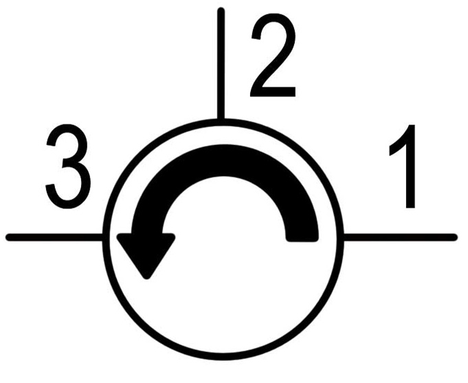
An optical circulator is built to pass light from one optical fiber to another. It is a non-reciprocal device routing the light based upon the direction of light propagation. Both optical circulator and optical isolator can be used to move light forward. However, there is typically more loss of light energy in the optical isolator than in the optical circulator. Optical circulator usually consists three ports: two ports are used as input ports and one port as output port. A signal is transmitted from port 1 to port 2, and another signal is transmitted from port 2 to port 3. Finally a third signal can be transmitted from port 3 to port 1. Many applications only require two, so they can be built to block any light that hits the third port.

optical-circulator-structure

Technologies of Optical Circulator Components

An optical circulator includes the components of Faraday rotator, birefringent crystal, waveplate, and beam displacer. The Faraday rotator uses the Faraday effect, which is a phenomenon that the polarization plane of an electromagnetic (light) wave is rotated in a material under a magnetic field applied parallel to the propagation direction of the lightwave. The light propagation in the birefringent crystal depends on the polarization state of the light beam and the relative orientation of the crystal. The polarization of the beam can be changed or the beam can be split into two beams with orthogonal polarization states. Waveplate and beam displacer are two different forms of birefringent crystal. A waveplate can be made by cutting a birefringent crystal to a particular orientation so that the optic axis of the crystal is in the incident plane and is parallel to the crystal boundary. Beam displacer is used to split an incoming beam into two beams with orthogonal polarization states.

Categories of Optical Circulator

According to polarization, optical circulator can be divided into polarization-dependent optical circulator and polarization-independent optical circulator. The former is used for the light with a particular polarization state, and the latter is not restricted to the polarization state of a light. Most of the optical circulators employed in fiber optic communications are designed to be polarization-independent.

According to functionality, optical circulator can be classified into full circulator and quasi-circulator. As mentioned before, full circulator makes full use of all ports in a complete circle. Light passes through from port 1 to port 2, port 2 to port 3, and port 3 back to port 1. About quasi-circulator, light passes through all ports sequentially but light from the last port is lost and cannot be transmitted back to the first port. For most applications, a quasi-circulator is enough.

Several Applications of Optical Circulator
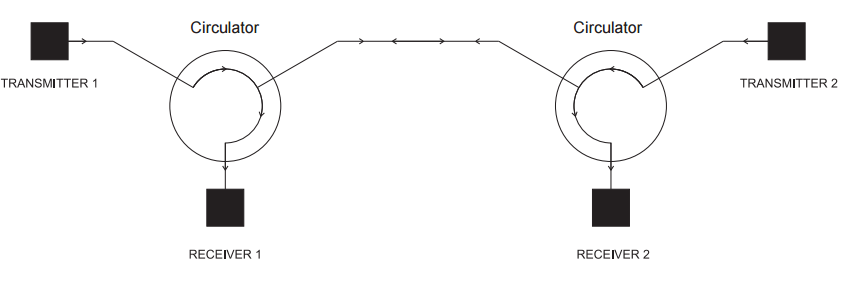
  • Duplex Transmitter/Receiver System: Optical circulators can be used to enable 2-way transmission along a single fiber. Transmitter 1 sends signal through Port 1 of Circulator 1 and through the fiber to Port 2 of Circulator 2 so that it is directed to Receiver 2. The signal from Transmitter 2 follows the opposite path to Receiver 1.

duplex-transmitte-receiver-system

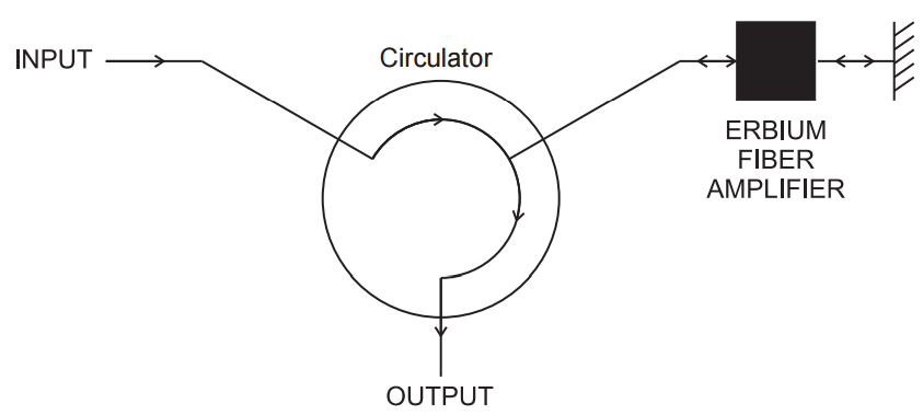
  • Double Pass Erbium Doped Amplifier: This technique allows high gain amplification of a signal through an erbium doped fiber amplifier. The signal passes through optical circulator and optical amplifier, returns from the fiber optic reflector and passes through the amplifier again. This amplified signal is directed through the return port.

double-pass-erbium-doped-amplifier

  • Wave Division Multiplexing System: Optical circulators in conjunction with Bragg gratings allow specific wavelengths to be reflected and sent down different paths.

wave-division-multiplexing-system

Conclusion

From this article, you may have a basic impression about optical circulator. It is an efficient and economical solution to use optical circulator for directing light signal with minimum loss. If you are interested in the optical circulator products, welcome to visit fs.com for more information.

Overview of PON Network

PON has now became a popular network technology all over the globe. It first came in to being in 1995. The International Telecommunication Union (ITU) standardized two initial generations of PON – APON and BPON. And the advancement of PON network has never stopped. Until now, the recent PON standard of NG-PON2 has been put forward in 2015. With the maturity of PON, people are more easily accessible to networks today. But what does PON exactly mean? What’s the composition of PON network? The following part will give you the answer.

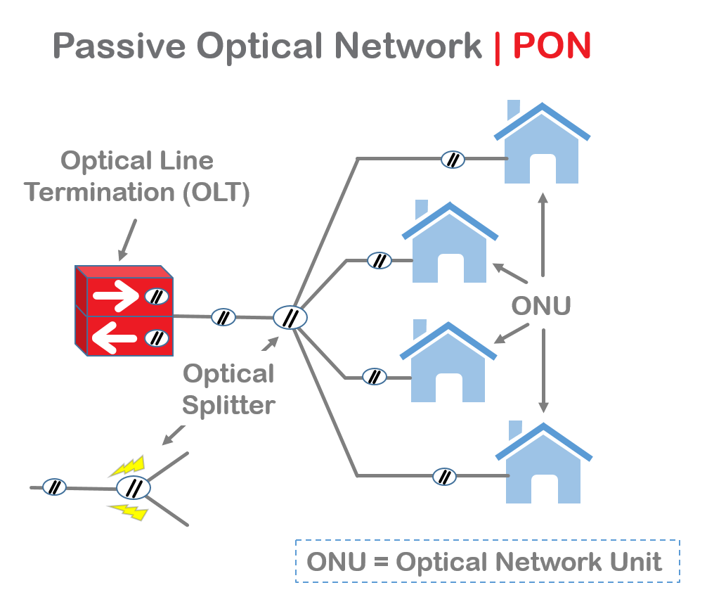
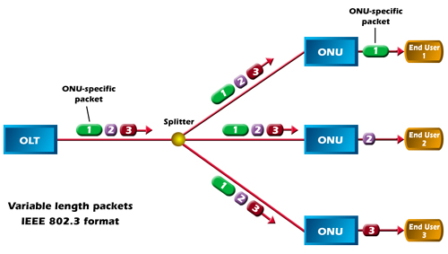
PON, also known as passive optical network, is a technology in telecommunication that implements a point-to-multipoint (P2MP) architecture. Unpowered fiber optic splitters are used to enable a single optical fiber to serve multiple end-points such as customers instead of providing individual fibers between the central office (hub) and customer. According to different terminations of PON, the network system can be divided into fiber-to-the-home (FTTH), fiber-to-the-curb (FTTC), fiber-to-the-curb (FTTB), etc. To be specific, a PON is made up of an optical line terminal (OLT) at the service provider’s hub and a number of optical network units (ONUs) or optical network terminals (ONTs) near end users. And “passive” is just used to describe that no power requirement or active electronic component is included for transmitting signals in the system.

PON network

Types of PON Network

Here are some types of PON that have been used throughout the years:

1) APON

Its full name is asynchronous transfer mode (ATM) passive optical network. As the original PON system, APON uses ATM technology to transfer data in packets or cells of a fixed size. In APON, downstream transmission is a continuous ATM stream at a bit rate of 155 Mbps or 622 Mbps. Upstream transmission is in the form of bursts of ATM cells at 155 Mbps.

2) BPON

BPON, also known as broadband PON, is the improved version of APON. It adopts wavelength division multiplexing (WDM) for downstream transmission with the transmission rate up to 622 Mbps. It also provides multiple broadband services such as ATM, Ethernet access and video distribution. Today, BPON is more popular than APON.

3) EPON

EPON or Ethernet PON uses the Ethernet packets instead of ATM cells. Upstream and downstream rates of EPON are able to achieve up to 10 Gbps. It is now widely applied to FTTP or FTTH architecture to serve multiple users. With the advantages of scalability, simplicity, multicast convenience and capability of providing full service access, many Asian areas adopt EPON for their networks.

4) GPON

Gigabit PON is the development of BPON. It supports various transmission rates with the same protocol. The maximum data rate of downstream is 2.5 Gbps and upstream is 1.25 Gbps. It is also widely used for FTTH networks. But compared with EPON, its burst sizes and physical layer overhead are smaller.

Advantages of PON

  • Low cost, simple maintenance, flexible extensibility and easy to upgrade. And no need for power during transmission saves a lot for long-term management.
  • Using pure media network avoids the interference of lightning and electromagnetism. Thus PON network is suitable for areas under harsh conditions.
  • Low occupancy of central office resources, low initial investment and high rate of return.
  • As the P2MP network, PON is able to provide a large range of service to plenty of users.

Conclusion

PON network is for sure an effective solution for multiple network users. EPON and GPON are the most commonly deployed PON systems at present. Since people have been seeking for higher bandwidth provisioning, the capability of transmission will be greatly improved in the near future.

Related Articles:
AON vs PON Networks: Which One to Choose for FTTH Systems
ABC of GPON SFP: Understanding GPON OLT / ONU / ONT SFP Module

40G Solutions: Duplex Fiber or MPO/MTP Fiber?

There’s been a lot of talk lately surrounding bidirectional 40 Gb/s duplex applications, or BiDi for short. Currently offered as a solution by Cisco®, BiDi runs over duplex OM3 or OM4 multimode fiber using QSFP modules and wavelength division multiplexing (WDM) technology. It features two 20 Gb/s channels, each transmitting and receiving simultaneously over two wavelengths on a single fiber strand – one direction transmitting in the 832 to 868 nanometer (nm) wavelength range and the other receiving in the 882 to 918 nm wavelength range. Avago Technologies also offers a similar QSFP BiDi transceiver.

Unidirectional 40 Gb/s duplex fiber solutions are available from Arista and Juniper. These differ from the BiDi solution in that they combine four 10 Gb/s channels at different wavelengths – 1270, 1290, 1310, and 1330 nm – over a duplex LC connector using OM3 or OM4 multimode or singlemode fiber. These unidirectional solutions are not interoperable with BiDi solutions because they use different WDM technology and operate within different wavelength ranges.

40G Solutions

While some of the transceivers used with these 40 Gb/s duplex fiber solutions are compliant with QSFP specifications and based on the IEEE 40GBASE- LR4 standard, there are currently no existing industry standards for 40 Gb/s duplex fiber applications using multiple wavelengths over multimode fiber – either bidirectional or unidirectional. There are standards-based 40 Gb/s applications over duplex singlemode fiber using WDM technology, but standards-based 40 Gb/s and 100 Gb/s applications over multimode use multi-fiber MPO/MTP connectors and parallel optics (40GBASE-SR4 and 100GBASE-SR4).

40 Gb/s duplex fiber solutions are promoted as offering reduced cost and installation time for quick migration to 40 Gb/s applications due to the ability to reuse the existing duplex 10 Gb/s fiber infrastructure for 40 Gb/s without having to implement MPO/MTP solutions. However, some of the concerns surrounding these non-standards based 40 Gb/s duplex fiber solutions include:

  • Lack of standards compliance and lack of interoperability with standards-based fiber solutions
  • Risk of being locked into a sole-sourced/proprietary solution that may have limited future support
  • BiDi and other 40 Gb/s duplex transceivers require significantly more power than standards-based solutions
  • Lack of application assurance due to operation outside of the optimal OM3/OM4 wavelength of 850 nm
  • Limited operating temperature range compared to standards-based solutions

Due to the aforementioned risks and limitations of using non-standards-based 40 Gb/s duplex fiber solutions, we recommends following industry standards and deploying 40GBASE-SR4 for 40 Gb/s applications today. While this standard requires multiple fibers using an MPO/MTP-based solution, it offers complete application assurance and interoperability, as well as overall lower power consumption.

Furthermore, TIA and IEC standards development is currently underway for wideband multimode fiber (WBMMF), which is expected to result in a new fiber type (potentially OM5 or OM4WB) that expands the capacity of multimode fiber over a wider range of wavelengths to support WDM technology. While not set in stone, the wavelengths being discussed within TIA working groups are 850, 880, 910, and 940 nm.

Unlike current 40 Gb/s duplex fiber applications, WBMMF will be a standards-based, interoperable technology that will be backwards compatible with existing OM4 fiber applications. WBMMF is expected to support unidirectional duplex 100 Gb/s fiber links using 25 Gb/s channels on 4 different wavelengths. WBMMF will also support 400 Gb/s using 25 Gb/s channels on 4 different wavelengths over 8 fibers, enabling existing MPO/MTP connectivity to be leveraged for seamless migration from current standards-based 40 Gb/s and 100 Gb/s applications to future standards-based 400 Gb/s applications.

Comparison Between EPON and GPON

PON is the abbreviation of passive optical network, which only uses fiber and passive components like fiber splitter and combiner. EPON (Ethernet PON) and GPON (Gigabit PON) are the most important versions of passive optical networks, widely used for Internet access, voice over Internet protocol (VoIP), and digital TV delivery in metropolitan areas. Today we are going to talk about the differences between EPON and GPON.

PON network(EPON and GPON)

Technology Comparison of EPON and GPON

EPON is based on the Ethernet standard 802.3 that can support the speed of 1.25 Gbit/s in both the downstream and upstream directions. It is well-known as the solution for the “first mile” optical access network. While GPON, based on Gigabit technology, is designated as ITU-T G.983 which can provide for 622 Mbit/s downstream and 155 Mbit/s upstream. GPON is an important approach to enable full service access network. Its requirements were set force by the Full Service Access Network (FASN) group, which was later adopted by ITU-T as the G.984.x standards–an addition to ITU-T recommendation, G.983, which details broadband PON (BPON).

As the parts of PON, they have something in common. For example, they both can be accepted as international standards, cover the same network topology methods and FTTx applications, and use WDM (wavelength-division multiplexing) with the same optical frequencies as each other with a third party wavelength; and provide triple-play, Internet Protocol TV (IPTV) and cable TV (CATV) video services.

Costs Comparison

No matter in a GPON or in an EPON, the optical line terminal (OLT), optical network unit (ONU) and optical distribution network (ODN) are the indispensable parts, which are the decisive factor of the costs of GPON and EPON deployments.

The cost of OLT and ONT is influenced by the ASIC (application specific integrated circuit) and optic module. Recently, the chipsets of GPON are mostly based on FPGA (field-programmable gate array), which is more expensive than the EPON MAC layer ASIC. On the other hand, the optic module’s price of GPON is also higher than EPON’s. When GPON reaches deployment stage, the estimated cost of a GPON OLT is 1.5 to 2 times higher than an EPON OLT, and the estimated cost of a GPON ONT will be 1.2 to 1.5 times higher than an EPON ONT.

We all know that the ODN is made up of fiber cable, cabinet, optical splitter, connector, and etc. In the case of transmitting signals to the same number of users, the cost of EPON and GPON would be the same.

Summary

Nowadays, since many experts have different opinions on EPON and GPON. Thus, there is no absolute answer to determine which is better. But one thing is clear: PON, which possesses the low cost of passive components, has made great strides driven by the growing demand for faster Internet service and more video. Also, fiber deployments will continue expanding at the expense of copper, as consumer demands for “triple-play” (video, voice and data) grow.

Related Articles:
EPON SFP VS. GPON SFP: Cost-effective Solution for Access Network
ABC of GPON SFP: Understanding GPON OLT / ONU / ONT SFP Module