Coherent Optics and 400G Applications

In today’s high-tech and data-driven environment, network operators face an increasing demand to support the ever-rising data traffic while keeping capital and operation expenditures in check. Incremental advancements in bandwidth component technology, coherent detection, and optical networking have seen the rise of coherent interfaces that allows for efficient control, lower cost, power, and footprint.

Below, we have discussed more about 400G, coherent optics, and how the two are transforming data communication and network infrastructures in a way that’s beneficial for clients and network service providers.

What is 400G?

400G is the latest generation of cloud infrastructure, which represents a fourfold increase in the maximum data-transfer speed over the current maximum standard of 100G. Besides being faster, 400G has more fiber lanes, which allows for better throughput (the quantity of data handled at a go). Therefore, data centers are shifting to 400G infrastructure to bring new user experiences with innovative services such as augmented reality, virtual gaming, VR, etc.

Simply put, data centers are like an expressway interchange that receives and directs information to various destinations, and 400G is an advancement to the interchange that adds more lanes and a higher speed limit. This not only makes 400G the go-to cloud infrastructure but also the next big thing in optical networks.

400G

What is Coherent Optics?

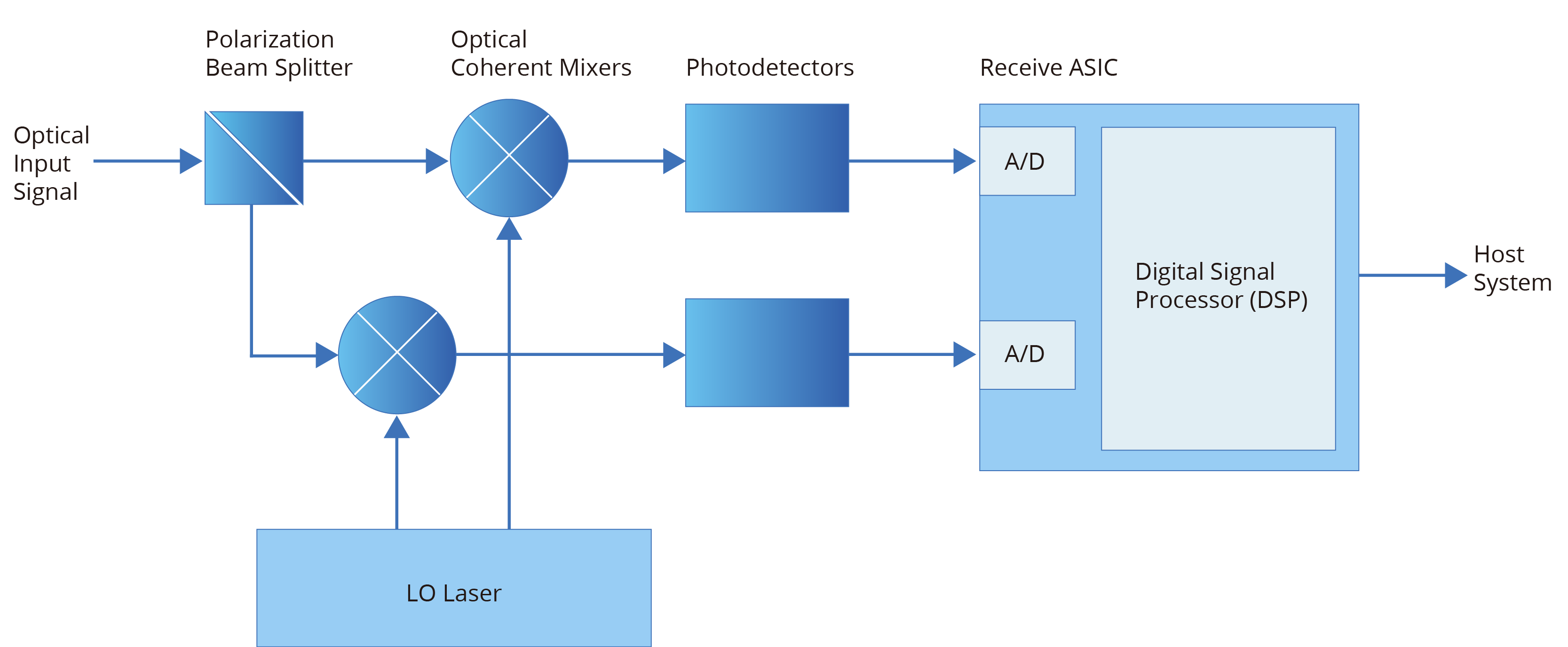
Coherent optical transmission or coherent optics is a technique that uses a variation of the amplitude and phase or segment of light and transmission across two polarizations to transport significantly more information through a fiber optic cable. Coherent optics also provides faster bit rates, greater flexibility, modest photonic line systems, and advanced optical performance.

This technology forms the basis of the industry’s drive to embrace the network transfer speed of 100G and beyond while delivering terabits of data across one fiber pair. When appropriately implemented, coherent optics solve the capacity issues that network providers are experiencing. It also allows for increased scalability from 100 to 400G and beyond for every signal carrier. This delivers more data throughput at a relatively lower cost per bit.

Coherent

Fundamentals of Coherent Optics Communication

Before we look at the main properties of coherent optics communication, let’s first understand the brief development of this data transmission technique. Ideally, fiber-optic systems came to market in the mid-1970s, and enormous progress has been realized since then. Subsequent technologies that followed sought to solve some of the major communication problems witnessed at the time, such as dispersion issues and high optical fiber losses.

And though coherent optical communication using heterodyne detection was proposed in 1970, it did not become popular because the IMDD scheme dominated the optical fiber communication systems. Fast-forward to the early 2000s, and the fifth-generation optical systems entered the market with one major focus – to make the WDM system spectrally efficient. This saw further advances through 2005, bringing to light digital-coherent technology & space-division multiplexing.

Now that you know a bit about the development of coherent optical technology, here are some of the critical attributes of this data transmission technology.

  • High-grain soft-decision FEC (forward error correction):This enables data/signals to traverse longer distances without the need for several subsequent regenerator points. The results are more margin, less equipment, simpler photonic lines, and reduced costs.
  • Strong mitigation to dispersion: Coherent processors accounts for dispersion effects once the signals have been transmitted across the fiber. The advanced digital signal processors also help avoid the headaches of planning dispersion maps & budgeting for polarization mode dispersion (PMD).
  • Programmability: This means the technology can be adjusted to suit a wide range of networks and applications. It also implies that one card can support different baud rates or multiple modulation formats, allowing operators to choose from various line rates.

The Rise of High-Performance 400G Coherent Pluggables

With 400G applications, two streams of pluggable coherent optics are emerging. The first is a CFP2-based solution with 1000+km reach capability, while the second is a QSFP DD ZR solution for Ethernet and DCI applications. These two streams come with measurement and test challenges in meeting rigorous technical specifications and guaranteeing painless integration and placement in an open network ecosystem.

When testing these 400G coherent optical transceivers and their sub-components, there’s a need to use test equipment capable of producing clean signals and analyzing them. The test equipment’s measurement bandwidth should also be more than 40-GHz. For dual-polarization in-phase and quadrature (IQ) signals, the stimulus and analysis sides need varying pulse shapes and modulation schemes on the four synchronized channels. This is achieved using instruments that are based on high-speed DAC (digital to analog converters) and ADC (analog to digital converters). Increasing test efficiency requires modern tools that provide an inclusive set of procedures, including interfaces that can work with automated algorithms.

Coherent Optics Interfaces and 400G Architectures

Supporting transport optics in form factors similar to client optics is crucial for network operators because it allows for simpler and cost-effective architectures. The recent industry trends toward open line systems also mean these transport optics can be plugged directly into the router without requiring an external transmission system.

Some network operators are also adopting 400G architectures, and with standardized, interoperable coherent interfaces, more deployments and use cases are coming to light. Beyond DCI, several application standards, such as Open ROADM and OpenZR+, now offer network operators increased performance and functionality without sacrificing interoperability between modules.

Article Source:Coherent Optics and 400G Applications

Related Articles:
Typical Scenarios for 400G Network: A Detailed Look into the Application Scenarios
How 400G Ethernet Influences Enterprise Networks?
ROADM for 400G WDM Transmission

400G Multimode Fiber: 400G SR4.2 vs 400G SR8

Cloud and AI applications are driving demand for data rates beyond 100 Gb/s, moving to high-speed and low-power 400 Gb/s interconnects. The optical fiber industry is responding by developing two IEEE 400G Ethernet standards, namely 400GBASE-SR4.2 and 400GBASE-SR8, to support the short-reach application space inside the data center. This article will elaborate on the two standards and their comparison.

400GBASE-SR4.2

400GBASE-SR4.2, also called 400GBASE-BD4.2, is a 4-pair, 2-wavelength multimode solution that supports reaches of 70m (OM3), 100m (OM4), and 150m (OM5). It is not only the first instance of an IEEE 802.3 solution that employs both multiple pairs of fibers and multiple wavelengths, but also the first Ethernet standard to use two short wavelengths to double multimode fiber capacity from 50 Gb/s to 100 Gb/s per fiber.

400GBASE-SR4.2 operates over the same type of cabling used to support 40GBASE-SR4, 100GBASE-SR4 and 200GBASE-SR4. It uses bidirectional transmission on each fiber, with each wavelength traveling in opposite directions. As such, each active position at the transceiver is both a transmitter and a receiver, which means 400GBASE-SR4.2 has eight optical transmitters and eight optical receivers in a bidirectional optical configuration.

The optical lane arrangement is shown as follows. The leftmost four positions labeled TR transmit wavelength λ1 (850nm) and receive wavelength λ2 (910nm). Conversely, the rightmost four positions labeled RT receive wavelength λ1 and transmit wavelength λ2.

400GBASE-SR4.2 fiber interface

400GBASE-SR8

400GBASE-SR8 is an 8-pair, 1-wavelength multimode solution that supports reaches of 70m (OM3), 100m (OM4 & OM5). It is the first IEEE fiber interface to use eight pairs of fibers. Unlike 400GBASE-SR4.2, it operates over a single wavelength (850nm) with each pair supporting 50 Gb/s transmission. In addition, it has two variants of optical lane arrangement. One variant uses the 24-fiber MPO, configured as two rows of 12 fibers, and the other interface variant uses a single-row MPO-16.

400GBASE-SR8 fiber interface variant 1
400GBASE-SR8 fiber interface variant 2

400GBASE-SR8 offers flexibility of fiber shuffling with 50G/100G/200G configurations. It also supports breakout at different speeds for various applications such as compute, storage, flash, GPU, and TPU. 400G-SR8 QSFP DD/OSFP transceivers can be used as 400GBASE-SR8, 2x200GBASE-SR4, 4x100GBASE-SR2, 8x50GBASE-SR.

400G SR4.2 vs. 400G SR8

As multimode solutions for 400G Ethernet, 400GBASE-SR4.2 and 400GBASE-SR8 share some features, but they also differ in a number of ways as discussed in the previous section.

The following table shows a clear picture of how they compare to each other.

 400GBASE-SR4.2400GBASE-SR8
AllianceIEEE 802.3cmIEEE 802.3cm (breakout: 802.3cd)
Max reach150m over OM5100m over OM4/OM5
Fibers8 fibers16 fibers (ribbon patch cord)
Wavelength2 wavelengths (850nm and 910nm)1 wavelength (850nm)
BiDi technologySupport/
Signal modulation formatPAM4 signalingPAM4 signaling
LaserVCSELVCSEL
Form factorQSFP-DD, OSFPQSFP-DD, OSFP

400GBASE-SR8 is technically simple but requires a ribbon patch cord with 16 fibers. It is usually built with 8 VCSEL lasers and doesn’t include any gearbox, so the overall cost of modules and fibers remains low. By contrast, 400GBASE-SR4.2 is technically more complex so the overall cost of related fibers or modules is higher, but it can support a longer reach.

In addition, 400GBASE-SR8 offers both flexibility and higher density. It supports fiber shuffling with 50G/100G/200G configurations and fanout at different I/O speeds for various applications. A 400G-SR8 QSFP-DD transceiver can be used as 400GBASE-SR8, 2x200GBASE-SR4, 4x100GBASE-SR2, or 8x50GBASE-SR.

400G SR4.2 & 400G SR8: Boosting Higher Speed Ethernet

As multimode fiber continues to evolve to serve growing demands for speed and capacity, both 400GBASE-SR4.2 and 400GBASE-SR8 help boost 400G Ethernet and scale up multimode fiber links too ensure the viability of optical solutions for various demanding applications.

The two IEEE 802.3cm standards provide a smooth evolution path for Ethernet, boosting cloud-based services and applications. Future advances point toward the ability to support even higher data rates as they are upgraded to the next level. The data center Industry will take advantage of the latest multimode fiber technology such as OM5 fiber, and use multiple wavelengths to transmit 100 Gb/s and 400 Gb/s over fibers over short reach of more than150 meters.

Beyond 2021-2022 timeframe, once an 800 Gb/s Ethernet standard is standardized, using more advanced technology with two-wavelength operation could create an 800 Gb/s, four-pair link. At the same time a single wavelength could support an 800 Gb/s eight-pair link. In this sense, 400GBASE-SR4.2 and 400GBASE-SR8 are setting the pace for a promising future.

Article Source: 400G Multimode Fiber: 400G SR4.2 vs 400G SR8

Related Articles:

400G Modules: Comparing 400GBASE-LR8 and 400GBASE-LR4
400G Optics in Hyperscale Data Centers
How 400G Has Transformed Data Centers

Importance of FEC for 400G


The rapid adoption of 400G technologies has seen a spike in bandwidth demands and a low tolerance for errors and latency in data transmission. Data centers are now rethinking the design of data communication systems to expand the available bandwidth while improving transmission quality.

Meeting this goal can be quite challenging, considering that improving one aspect of data transmission consequently hurts another. However, one solution seems to stand out from the rest as far as enabling reliable, efficient, and high-quality data transmission is concerned. We’ve discussed more on Forward Error Correction (FEC) and 400G technology in the sections below, including the FEC considerations for 400Gbps Ethernet.

What Is FEC?

Forward Error Correction is an error rectification method used in digital signals to improve data reliability. The technique is used to detect and correct errors in data being transmitted without retransmitting the data.

FEC introduces redundant data and the error-correcting code before data transmission is done. The redundant bits/data are complex functions of the original information and are sent multiple times since an error can appear in any transmitted samples. The receiver then corrects errors without requesting retransmission of the data by acknowledging only parts of the data with no apparent errors.

FEC codes can also generate bit-error-rate signals used as feedback to fine-tune analog receiving electronics. The FEC code design determines the number of missing bits that can be corrected. Block codes and convolutional codes are the two FEC code categories that are widely used. Convolutional codes handle arbitrary-length data and use the Viterbi algorithm for decoding purposes. On the other hand, block codes handle fixed-size data packets, and partial code blocks are decoded in polynomial time to the code block length.

FEC

What Is 400G?

This is the next generation of cloud infrastructure widely used by high-traffic volume data centers, telecommunication service providers, and other large enterprises with relentless data transmission needs. The rapidly increasing network traffic has seen network carriers continually face bandwidth challenges. This exponential sprout in traffic is driven by the increased deployments of machine learning, cloud computing, artificial intelligence (AI), and IoT devices.

Compared to the previous 100G solution, 400G, also known as 400GbE or 400GB/s, is four times faster. This Terabit Ethernet transmits data at 400 billion bits per second, i.e., in optical wavelength; hence it’s finding application in high-speed, high-performance deployments.

The 400G technology also delivers the power, data density, and efficiency required for cutting-edge technologies such as virtual reality (VR), augmented reality (AR), 5G, and 4K video streaming. Besides consuming less power, the speeds also support scale-out and scale-up architectures by providing high density, low-cost-per-bit, and reliable throughput.

Why 400G Requires FEC

Several data centers are adopting 400 Gigabit Ethernet, thanks to the faster network speeds and expanded use cases that allow for new business opportunities. This 400GE data transmission standard uses the PAM4 technology, which offers twice the transmission speed of NRZ technology used for 100GE.

The increased speed and convenience of PAM4 also come with its own challenges. For instance, the PAM4 transmission speed is twice as fast as that of NRZ, but the signal levels are half that of 100G technology. This degrades the signal-to-noise ratio (SNR); hence 400G transmissions are more susceptible to distortion.

Therefore, forward error correction (FEC) is used to solve the waveform distortion challenge common with 400GE transmission. That said, the actual transmission rate of a 400G Ethernet link is 425Gbps, with the additional 25 bits used in establishing the FEC techniques. 400GE elements, such as DR4 and FR4 optics, have transmission errors, which FEC helps rectify.

FEC Considerations for 400Gbps Ethernet

With the 802.3bj standards, FEC-related latency is often targeted to be equal to or less than 100ns. Here, the receive time for FEC-frame takes approximately 50ns, with the rest time budget used for decoding. This FEC latency target is practical and achievable.

Using similar/same FEC code for the 400GbE transmission makes it possible to achieve lower latency. But when a higher coding gain FEC is required, e.g., at the PMD level, one can trade off FEC latency for the desired coding gain. It’s therefore recommended to keep a similar latency target (preferably 100ns) while pushing for a higher coding gain of FEC.

Given that PAM4 modulation is used, FEC’s target coding gain (CG) could be over 8dB. And since soft-decision FEC comes with excessive power consumption, it’s not often preferred for 400GE deployments. Similarly, conventional block codes with their limited latency need a higher overclocking ratio to achieve the target.

Assuming that a transcoding scheme similar to that used in 802.3bj is included, the overclocking ratio should be less than 10%. This helps minimize the line rate increase while ensuring sufficient coding gain with limited latency.

So under 100ns latency and less than 10% overclocking ratio, FEC codes with about 8.5dB coding gain are realizable for 400GE transmission. Similarly, you can employ M (i.e., M>1) independent encoders for M-interleaved block codes instead of using parallel encoders to achieve 400G throughput.

Conclusion

400GE transmission offers several benefits to data centers and large enterprises that rely on high-speed data transmission for efficient operation. And while this 400G technology is highly reliable, it introduces some transmission errors that can be solved effectively using forward error correction techniques. There are also some FEC considerations for 400G Ethernet, most of which rely on your unique data transmission and network needs.


Article Source: Importance of FEC for 400G

Related Articles:
How 400G Ethernet Influences Enterprise Networks?
How Is 5G Pushing the 400G Network Transformation?
400G Transceiver, DAC, or AOC: How to Choose?

400G Data Center Deployment Challenges and Solutions

As technology advances, specific industry applications such as video streaming, AI, and data analytics are increasingly pushing for increased data speeds and massive bandwidth demands. 400G technology, with its next-gen optical transceivers, brings a new user experience with innovative services that allow for faster and more data processing at a time.

Large data centers and enterprises struggling with data traffic issues embrace 400G solutions to improve operational workflows and ensure better economics. Below is a quick overview of the rise of 400G, the challenges of deploying this technology, and the possible solutions.

The Rise of 400G Data Centers

The rapid transition to 400G in several data centers is changing how networks are designed and built. Some of the key drivers of this next-gen technology are cloud computing, video streaming, AI, and 5G, which have driven the demand for high-speed, high-bandwidth, and highly scalable solutions. The large amount of data generated by smart devices, the Internet of Things, social media, and other As-a-Service models are also accelerating this 400G transformation.

The major benefits of upgrading to a 400G data center are the increased data capacity and network capabilities required for high-end deployments. This technology also delivers more power, efficiency, speed, and cost savings. A single 400G port is considerably cheaper than four individual 100G ports. Similarly, the increased data speeds allow for convenient scale-up and scale-out by providing high-density, reliable, and low-cost-per-bit deployments.

How 400G Works

Before we look at the deployment challenges and solutions, let’s first understand how 400G works. First, the actual line rate or data transmission speed of a 400G Ethernet link is 425 Gbps. The extra 25 bits establish a forward error connection (FEC) procedure, which detects and corrects transmission errors.

400G adopts the 4-level pulse amplitude modulation (PAM4) to combine higher signal and baud rates. This increases the data rates four-fold over the current Non-Return to Zero (NRZ) signaling. With PAM4, operators can implement four lanes of 100G or eight lanes of 50G for different form factors (i.e., OSFP and QSFP-DD). This optical transceiver architecture supports transmission of up to 400 Gbit/s over either parallel fibers or multiwavelength.

PM4
PAM4

Deployment Challenges & Solutions

Interoperability Between Devices

The PAM4 signaling introduced with 400G deployments creates interoperability issues between the 400G ports and legacy networking gear. That is, the existing NRZ switch ports and transceivers aren’t interoperable with PAM4. This challenge is widely experienced when deploying network breakout connections between servers, storage, and other appliances in the network.

400G transceiver transmits and receives with 4 lanes of 100G or 8 lanes of 50G with PAM4 signaling on both the electrical and optical interfaces. However, the legacy 100G transceivers are designed on 4 lanes of 25G NRZ signaling on the electrical and optical sides. These two are simply not interoperable and call for a transceiver-based solution.

One such solution is the 100G transceivers that support 100G PAM4 on the optical side and 4X25G NRZ on the electrical side. This transceiver performs the re-timing between the NRZ and PAM4 modulation within the transceiver gearbox. Examples of these transceivers are the QSFP28 DR and FR, which are fully interoperable with legacy 100G network gear, and QSFP-DD DR4 & DR4+ breakout transceivers. The latter are parallel series modules that accept an MPO-12 connector with breakouts to LC connectors to interface FR or DR transceivers.

NRZ & PM4
Interoperability Between Devices

Excessive Link Flaps

Link flaps are faults that occur during data transmission due to a series of errors or failures on the optical connection. When this occurs, both transceivers must perform auto-negotiation and link training (AN-LT) before data can flow again. If link flaps frequently occur, i.e., several times per minute, it can negatively affect throughput.

And while link flaps are rare with mature optical technologies, they still occur and are often caused by configuration errors, a bad cable, or defective transceivers. With 400GbE, link flaps may occur due to heat and design issues with transceiver modules or switches. Properly selecting transceivers, switches, and cables can help solve this link flaps problem.

Transceiver Reliability

Some optical transceiver manufacturers face challenges staying within the devices’ power budget. This results in heat issues, which causes fiber alignment challenges, packet loss, and optical distortions. Transceiver reliability problems often occur when old QSFP transceiver form factors designed for 40GbE are used at 400GbE.

Similar challenges are also witnessed with newer modules used in 400GbE systems, such as the QSFP-DD and CFP8 form factors. A solution is to stress test transceivers before deploying them in highly demanding environments. It’s also advisable to prioritize transceiver design during the selection process.

Deploying 400G in Your Data Center

Keeping pace with the ever-increasing number of devices, users, and applications in a network calls for a faster, high-capacity, and more scalable data infrastructure. 400G meets these demands and is the optimal solution for data centers and large enterprises facing network capacity and efficiency issues. The successful deployment of 400G technology in your data center or organization depends on how well you have articulated your data and networking needs.

Upgrading your network infrastructure can help relieve bottlenecks from speed and bandwidth challenges to cost constraints. However, making the most of your network upgrades depends on the deployment procedures and processes. This could mean solving the common challenges and seeking help whenever necessary.

A rule of thumb is to enlist the professional help of an IT expert who will guide you through the 400G upgrade process. The IT expert will help you choose the best transceivers, cables, routers, and switches to use and even conduct a thorough risk analysis on your entire network. That way, you’ll upgrade appropriately based on your network needs and client demands.
Article Source: 400G Data Center Deployment Challenges and Solutions
Related Articles:

NRZ vs. PAM4 Modulation Techniques
400G Multimode Fiber: 400G SR4.2 vs 400G SR8
Importance of FEC for 400G

NRZ vs. PAM4 Modulation Techniques

The leading trends such as cloud computing and big data drive the exponential traffic growth and the rise of 400G Ethernet. Data center networks are facing a larger bandwidth demand, and innovative technologies are required for infrastructure to meet shifting demands. Currently, there are two different signal modulation techniques examined for next-generation Ethernet: non-return to zero (NRZ), and pulse-amplitude modulation 4-level (PAM4). This article will take you through these two modulation techniques and compare them to find the optimal choice for 400G Ethernet.

NRZ and PAM4 Basics

NRZ is a modulation technique using two signal levels to represent the 1/0 information of a digital logic signal. Logic 0 is a negative voltage, and Logic 1 is a positive voltage. One bit of logic information can be transmitted or received within each clock period. The baud rate, or the speed at which a symbol can change, equals the bit rate for NRZ signals.

NRZ
NRZ

PAM4 is a technology that uses four different signal levels for signal transmission and each symbol period represents 2 bits of logic information (0, 1, 2, 3). To achieve that, the waveform has 4 different levels, carrying 2 bits: 00, 01, 10 or 11, as shown below. With two bits per symbol, the baud rate is half the bit rate.

PAM4
PAM4

Comparison of NRZ vs. PAM4

Bit Rate

A transmission with NRZ mechanism will have the same baud rate and bitrate because one symbol can carry one bit. 28Gbps (gigabit per second) bitrate is equivalent to 28GBdps (gigabaud per second) baud rate. While, because PAM4 carries 2 bits per symbol, 56Gbps PAM4 will have a line transmission at 28GBdps. Therefore, PAM4 doubles the bit rate for a given baud rate over NRZ, bringing higher efficiency for high-speed optical transmission such as 400G. To be more specific, a 400 Gbps Ethernet interface can be realized with eight lanes at 50Gbps or four lanes at 100Gbps using PAM4 modulation.

Signal Loss

PAM4 allows twice as much information to be transmitted per symbol cycle as NRZ. Therefore, at the same bitrate, PAM4 only has half the baud rate, also called symbol rate, of the NRZ signal, so the signal loss caused by the transmission channel in PAM4 signaling is greatly reduced. This key advantage of PAM4 allows the use of existing channels and interconnects at higher bit rates without doubling the baud rate and increasing the channel loss.

Signal-to-noise Ratio (SNR) and Bit Error Rate (BER)

According to the following figure, the eye height for PAM4 is 1/3 of that for NRZ, causing the PAM4 to increase SNR (Signal-Noise Ratio) by -9.54 dB (Link Budget Penalty), which impacts the signal quality and introduces additional constraints in high-speed signaling. The 33% smaller vertical eye opening makes PAM4 signaling more sensitive to noise, resulting in a higher bit error rate. However, PAM4 was made possible because of forward-error correction (FEC) that can help link system to achieve the desired BER.

NRZ vs. PAM4
NRZ vs. PAM4

Power Consumption

Reducing BER in a PAM4 channel requires equalization at the Rx end and pre-compensation at the Tx end, which both consume extra power than the NRZ link for a given clock rate. This means PAM4 transceivers generate more heat at each end of the link. However, the new state-of-the-art silicon photonics (SiPh) platform can effectively reduce energy consumption and can be used in 400G transceivers. For example, FS silicon photonics 400G transceiver combines SiPh chips and PAM4 signaling, making it a cost-effective and lower power consumption solution for 400G data center.

Shift from NRZ to PAM4 for 400G Ethernet

With massive data transmitted across the globe, many organizations pose their quest for migration towards 400G. Initially, 16× 25G baud rate NRZ is used for 400G Ethernet, such as 400G-SR16, but the link loss and size of the scheme can not meet the demands of 400G Ethernet. Whereas PAM4 enables higher bit rates at half the baud rate, designers can continue to use existing channels at potential 400G Ethernet data rates. As a result, PAM4 has overtaken NRZ as the preferred modulation method for electrical or optical signal transmission in 400G optical modules.

Article Source: NRZ vs. PAM4 Modulation Techniques

Related Articles:
400G Data Center Deployment Challenges and Solutions
400G ZR vs. Open ROADM vs. ZR+
400G Multimode Fiber: 400G SR4.2 vs 400G SR8