Guide to Optical Amplifier

Optical amplifier is an significant device deployed for optical communication and laser physics. No need for converting optical signals into electrical signals first, optical amplifier can directly amplify the optical signals. It is considered to be a laser without optical cavity or with suppressed feedback from cavity. Optical amplifiers are often installed at places where optical signals are weak and need to be enhanced. This ensures the stable transmission of optical signals in the rest cables. Thus, we should attach greater importance to optical amplifier. And this article will guide you to know the secrets of optical amplifier.

optical-amplifier

Functions of Optical Amplifier

In an optical network, optical amplifiers can be used as booster amplifiers, pre-amplifiers or inline amplifiers. These functions are a little different from each other. When a optical amplifier acts as a booster, it is used to amplify the signals that leave the transmitter into the required level before entering into fiber links. The booster amplifier is especially important to a WDM link as the multiplexer attenuates optical signals. Pre-amplifier is used at the other end of a link to amplify the signal level for it to be detected over or above the thermal noise of the receiver. As for inline amplifier, it is used for links over 150 km in case signals become weak in long distance. Every 80 to 100 km, inline amplifier will be placed to make sure that the signal level is over the noise floor.

optical-amplifier-function

Three Types of Optical Amplifiers
1) Erbium Doped Fiber Amplifier (EDFA)

Erbium doped fiber amplifier or EDFA is now the most widely used optical amplifier for long range fiber communications. Its optical fiber (usually a single-mode fiber) at the core is doped with rare earth element erbium to absorb light at one frequency and emit light at another frequency. The light is pumped from laser diodes with a wavelength around 980 nm and sometimes around 1480 nm. EDFA has advantages of high gain, wide bandwidth, high output power, high pumping efficiency, low insertion loss and insensitive to polarization state which turns out to be a good solution for DWDM, CATV and SDH applications.

2) Roman Amplifier

Roman amplifier is designed based on the Roman gain which results from the effect of stimulated Roman scattering. When a lower frequency signal photon induces the inelastic scattering of a higher-frequency pump photon in an optical medium in the nonlinear regime, another signal photon is produced with the surplus energy resonantly passed to the vibrational states of the medium. Roman amplifier is often installed in the mid-stream of a signal or in front of the receiver to amplify signal levels. It has the advantages of greater operating wavelength range, constant optical gain and effective noise figure reduction.

3) Semiconductor Optical Amplifier (SOA)

Semiconductor optical amplifier or SOA is the optical amplifier based on a semiconductor gain medium. Light is sent through a semiconductor single-mode waveguide with transverse dimensions. SOA is usually connected to the output of 1310nm transceivers to amplify signal level before entering into optical fiber. It supports all format of 1310nm wavelength signals and is compatible with all data rates. Thus, SOA is an ideal solution for DWDM network optical amplification.

Conclusion

To sum up, optical amplifier enables the optical transmission over long distance by amplifying signals. This article introduces the fundamentals of its functions and some commonly used types. You may have an overall understanding about optical amplifier. For more information, please visit FS.COM.

Important Components in DWDM System

Dense wavelength division multiplexing (DWDM) is one of the most recent and important technologies in the development of fiber optic transmission technology. Its most obvious advantage is the ability to provide potentially unlimited transmission capacity. In a DWDM system, there are four important components, which are optical transmitter/receiver, DWDM Mux/Demux filter, optical add/drop multiplexer (OADM) and optical amplifier. This article will give an introduction to these four components respectively.

Optical Transmitter/Receiver

As a highly important part of the DWDM system, the optical transmitter/receiver is responsible for providing source signals and receiving signals. Multiple optical transmitters are used as the light sources in a DWDM system. The lasers on the transmit side create pulses of light. Each light pulse has an exact wavelength which shall be precise and stable.

As the development of fiber optic transmission technology, the optical transmitter/receiver has been gradually replaced by the optical transceiver. Optical transceiver is a device comprising both a transmitter and a receiver which are combined and share common circuitry or a single housing. There is another device named transponder used in the DWDM system sometimes. It has the similar principle with the optical transceiver. Both optical transceivers and transponders have the function of optical-electrical-optical (O-E-O) conversion. The main difference between them is that the interface of optical transceivers is serial, while the interface of transponders is parallel.

DWDM Mux/Demux Filters

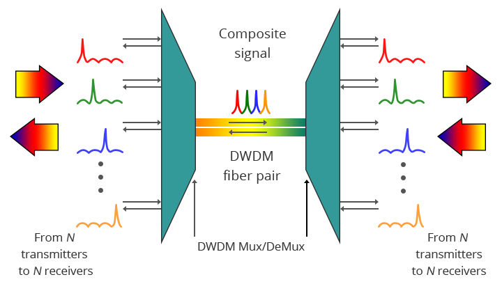
It is known to us that multiple wavelengths created by multiple transmitters operate on different fibers. The role of optical filter (multiplexer filter) is to combine these multiple wavelengths onto one fiber. The output signal of an optical multiplexer is referred to as a composite signal. Then an optical drop filter (demultiplexer) at the receiving end performs the function of separating out all the individual wavelengths of the composite signal to individual fibers. One thing needed to be noted is that the demultiplexing process should be done before the light is detected. The following figure shows a bidirectional DWDM operation. N light pulses of N different wavelengths carried by N different fibers are combined by a DWDM Mux. A DWDM Demux receives the composite signal and separates each of the N component signals and passes each to a fiber.

DWDM system

DWDM OADM

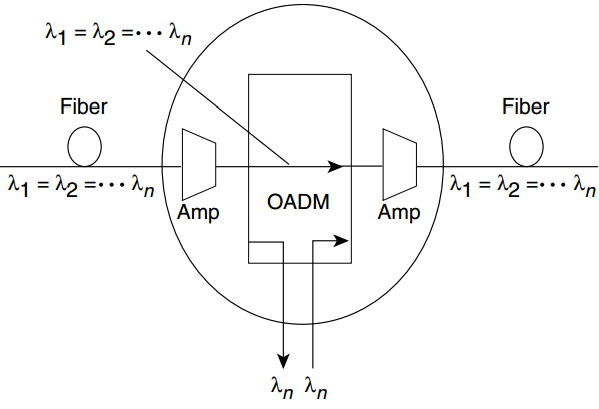
In the DWDM system, there is an area in which multiple wavelengths exist between multiplexing and demultiplexing points. And it is desirable that one or more wavelengths at some point along this span can be added or dropped. The OADM is designed for this function. Rather than combining or separating all wavelengths, the OADM can remove some of the wavelengths and allow the other wavelengths to pass on. The following figure shows the add-drop process of OADM (“Amp” represents for amplification, “λ” represents for wavelength).

the add-drop process of OADM

Optical Amplifier in DWDM System

Since the DWDM system is for long transmission links, the signals must be amplified after a certain fiber length. As a kind of “in-fiber” device, optical amplifier boosts the amplitude or add gain to optical signals passing on a fiber through the way of directly stimulating the photons of the signal with extra energy. Optical amplifier can amplify optical signals across a broad range of wavelengths, which is very important for DWDM system application. The commonly used in-fiber amplifier is erbium-doped fiber amplifier (EDFA).

Continuing to provide the bandwidth for large amounts of data, DWDM system is now becoming the basis of all-optical networking with wavelength provisioning and mesh-based protection.

Related Articles:
Why Is EDFA (Erbium Doped Fiber Amplifier) Essential To DWDM Systems?
DWDM Solutions for Metropolitan Area Network

The Application of EDFA

Optical amplifiers are the critical technology for the optical communication networks, enabling the transmission of many terabits of data over distances from a few hundred kilometers to thousands of kilometers by overcoming the fiber loss limitation. As the first optical amplifier commonly used in optical communications systems, EDFA has resulted in a dramatic growth in transmission capacity with the deployment of WDM systems. Be equipped with the features of high output power, high gain, wide bandwidth, polarization independence and low noise figure, EDFAs have become one of the key components used in the new-generation optical communication system. So what is EDFA? Do you know EDFA working principle?

What Is EDFA?

Erbium-doped fiber amplifier (EDFA) is an optical repeater device that is utilized to boost the intensity of optical signals being carried through a fiber optic communications system. An optical fiber is doped with the rare earth element erbium so that the glass fiber can absorb light at one frequency and emit light at another frequency.

EDFA Working Principle

The erbium-doped fiber (EDF) is at the core of EDFA technology, which is a conventional silica fiber doped with Erbium. When the Erbium is illuminated with light energy at a suitable wavelength (either 980 nm or 1480 nm), it is motivated to a long-lifetime intermediate state, then it decays back to the ground state by emitting light within the 1525-1565 nm band. The Erbium can be either pumped by 980 nm light, in which case it passes through an unstable short lifetime state before rapidly decaying to a quasi-stable state, or by 1480 nm light in which case it is directly excited to the quasi-stable state. Once in the quasi-stable state, it decays to the ground state by emitting light in the 1525-1565 nm band. This decay process can be stimulated by pre-existing light, thus resulting in amplification. EDFA working principle is shown in the Figure 1.

EDFA working principle

Figure 1: EDFA working principle.

Baisc configuration of EDFA

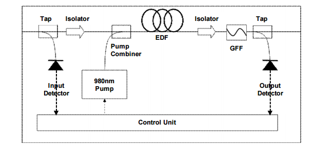
EDFA configuration is mainly composed of an EDF, a pump laser, and a component (often referred to as a WDM) for combining the signal and pump wavelength so that they can propagate simultaneously through the EDF. In principle, EDFAs can be designed such that pump energy propagates in the same direction as the signal (forward pumping), the opposite direction to the signal (backward pumping), or both direction together. The pump energy may either be 980 nm pump energy, 1480 nm pump energy, or a combination of both. Practically, the most common EDFA configuration is the forward pumping configuration using 980 nm pump energy, as shown in the Figure 2.

EDFA-configuration

Figure 2: The EDFA configuration with 980 nm pump energy

Application of EDFA

After learning what is EDFA, and EDFA working principle. Next, we’ll discuss application forms and application fields of EDFA.

Forms of application
  • Booster Amplifier

When used as the booster amplifier, EDFA is deployed in the output of an optical transmitter to improve the output power of the multi-wavelength signal having been multiplexed, as shown in Figure 3. In this way, distances of optical communication transmission can be extended. This application form places a demand of higher output power on EDFA.

The booster amplifier

Figure 3: The booster amplifier

  • Preamplifier

When used as the preamplifier, EDFA needs the features of low noise and high gain. Being equipped with these features, EDFA can significantly improve the sensitivity of an optical receiver when deployed in the input of an optical receiver, as shown in Figure 4.

The preamplifier

Figure 4: The preamplifier

  • Line Amplifier

When used as the line amplifier, EDFA is able to periodically compensate for the transmission loss of lines. As a substitute for OEO repeater, EDFA can directly amplify the optical signals transmitted in lines. In this way, we solve the bottleneck problems of photoelectric interchange to lay a foundation for all-optical network (AON). Figure 5 shows this application of EDFA.

The line amplifier

Figure 5: The line amplifier

Fields of application

EDFA has the following fields of application:

(1) EDFA can be employed in the high-capacity and high-speed optical communication system. The application of EDFA is very constructive to deal with the problems of low sensitivity of receivers and short transmission distances owing to a lack of OEO repeater.

(2) EDFA can be utilized in long-haul optical communication system. By utilizing EDFA, we can dramatically lower construction cost by increasing the repeater spacing to reduce the quantity of regenerative repeaters. The long-haul optical communication system mainly includes the land trunk optical transmission system and the submarine optical fiber cable transmission system.

(3) EDFA can be used in the optical fiber subscriber access network system. If the transmission distances are too long, EDFA will function as the line amplifier to compensate for the transmission losses of lines, thus greatly increasing the number of subscribers.

(4) EDFA can be employed in wavelength-division multiplexing (WDM) system, especially dense wavelength-division multiplexing (DWDM) system. Utilization of EDFA in WDM system is able to solve the problems of insertion loss and reduce the influences of chromatic dispersion.

(5) EDFA can be utilized in community antenna television (CATV) system. In CATV system, EDFA functions as the booster amplifier to greatly improve the input power of an optical transmitter. Utilizing EDFA to compensate for the insertion loss of optical power splitters can significantly enlarge the scale of the distribution network and increase the number of subscribers.

Conclusion

From the above, we have a good understanding of EDFA, including EDFA working principle and its application. Of the various technologies available for optical amplifiers, EDFA technology is by far the most advanced. Nowadays EDFA is extensively in the optical fiber communication networks. As communication technologies continue to be developed, EDFA will become the preferred choice for the future optical amplifiers. Being equipped with the features of flat gain over a large dynamic gain range, low noise, high saturation output power and stable operation with excellent transient suppression, EDFA will play a more and more important role in optical communication system to better serve subscribers.

Related Articles:
Optical Amplifier – EDFA (Erbium-doped Fiber Amplifier) for WDM System
Differences Between Pre-Amplifier, Booster Amplifier and In-line Amplifier

Introdution To Optical Amplifiers

1. Introduction:
Optical amplifiers, as the key technology for optical communication networks, have made it possible to transmit many terabits of data over distances from a few hundred kilometers and up to transoceanic distances with wavelength-division multiplexing (WDM) technology, which allows the transmission of multiple channels over the same fiber. The transmission distance of any optical fiber communication system is eventually limited by fiber losses.Optical amplifiers overcome the loss limitation by amplifying the entire WDM signals in strength by several orders of magnitude without requiring conversion of each channel to the electric domain, thus permitting a dramatic increase in capacity of the transmission system and providing the data capacity required for current and future communication networks. The purpose of this passage is to provide an overview of optical amplifiers.

2. The Practical Principles of Optical Amplifiers
A basic optical communication link is composed of a transmitter and receiver, with an optical fiber cable connecting them. Although signals propagating in optical fibers suffer far less attenuation than in other mediums, such as copper, there is still a limit of about 100 km on the distance the signals can travel before becoming too noisy to be detected. Before the advent of optical amplifiers, it was essential to electronically regenerate the optical signals every 80-100 km in order to accomplish transmission over long distances. Although feasible when transmitting a single low-capacity optical channel, it becomes unfeasible when transmitting tens of high-capacity WDM channels, thus resulting in an expensive, powerhungry and bulky regenerator station,

A optical amplifier is designed to directly amplify any input optical signal, without transforming it first to an electronic signal. It can amplify all WDM channels together, and is generally transparent to the number of channels, their bit-rate, protocol, and modulation format. So a single optical amplifier can replace all the multiple components required for an electronic regeneration station. What’s more, the transparency of the optical amplifier means that the link can be upgraded without the need to replace the amplifier.

Optical amplifiers are extensively applied in the optical communication links. Figure 1 shows three ways in which optical amplifiers can be used to enhance the performance of optical communication links. A booster amplifier is used to increase the optical output of an optical transmitter just before a signal enters an optical fiber. The optical signal is attenuated as it travels in the optical fiber. An inline amplifier is used to restore the optical signal to its original power level. An optical pre-amplifier is used at the end of the optical fiber link in order to increase the sensitivity of an optical receiver.
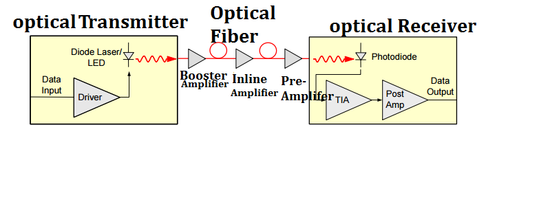
Optical-amplifiers-in-a-optical-communication-link

Figure 1: Optical amplifiers in a optical communication link

3.Types of Optical Amplifiers
There are three most important types of optical amplifiers used in the optical communication network: the erbium-doped fiber amplifier (EDFA), the semiconductor optical amplifier (SOA), and the fiber Raman amplifier (FRA). Each of these amplifiers is introduced as follows.

3.1 Erbium-doped fiber amplifiers
As the first optical amplifier widely used in optical communications systems, EDFA has resulted in a dramatic growth in transmission capacity with the deployment of WDM systems. EDFAs are very widely deployed and become the basis of the vast majority of optically amplified systems. EDFA is an optical repeater device that is used to boost the intensity of optical signals being carried through a fiber optic communications system.

The erbium-doped fiber (EDF) is at the core of EDFA technology, which is a conventional silica fiber doped with erbium. When the erbium is illuminated with light energy at a suitable wavelength (either 980nm or 1480nm), it is motivated to a long-lifetime intermediate state (see Figure 2), then it decays back to the ground state by emitting light within the 1525-1565 nm band. The erbium can be either pumped by 980nm light, in which case it pass through an unstable short lifetime state before rapidly decaying to a quasi-stable state, or by 1480nm light in which case it is directly excited to the quasi-stable state. Once in the quasi-stable state, it decays to the ground state by emitting light in the 1525-1565nm band. This decay process can be stimulated by pre-existing light, thus resulting in amplification.
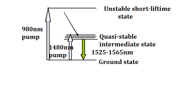
Pracital-principle-of-EDFA

Figure 2:The practical principle of EDFA

In generally, a EDFA consist of a EDF, a pump laser, and a component (often referred to as a WDM) for combining the signal and pump wavelength so that they can propagate simultaneously through the EDF. In principle EDFAs can be designed such that pump energy propagates in the same direction as the signal (forward pumping), the opposite direction to the signal (backward pumping), or both direction together. The pump energy may either by 980nm pump energy, 1480nm pump energy, or a combination of both. Practically, the most common EDFA configuration is the forward pumping configuration using 980nm pump energy, as shown in Figure 3.
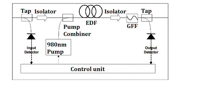
EDFA-configuration

Figure 3: The EDFA configuration

3.2 Semiconductor optical amplifiers
SOAs are amplifiers which use a semiconductor to provide the gain medium. A semiconductor optical amplifier is illustrated in Figure 4. The gain medium is the undoped InGaAsP. This material can be tailored to provide optical amplification at wavelength near 1.3 µm or near 1.5 µm, which is the significant wavelength for optical communications. Other semiconductors can be used to amplify optical signals at other wavelengths. The input and output faces of the amplifier are antireflection-coated in order to prevent optical feedback to the gain medium and lasing.
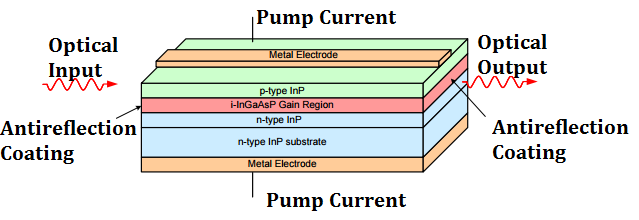
A-semiconductor-optical-amplifier

Figure 4: A semiconductor optical amplifier

SOAs operate in a similar way to standard semiconductor lasers (without optical feedback which causes lasing), and are packaged in small semiconductor “butterfly” packages. Unlike other optical amplifiers, they are pumped electronically and a separate pump laser is not required. SOAs are less expensive and therefore suitable for using in local networks where best performance is not required but cost is an important factor.Despite their small size and potentially low cost due to mass production, SOAs suffer from a number of drawbacks which make them unsuitable for most applications. In particular, they provide relatively low gain, have a low saturated output power and relatively high noise factor (NF). These drawbacks makes SOAs unsuitable for multichannel application but fit for some single channel which don’t require high gain and high output power.

3.3 Fiber Raman amplifiers
A fiber Raman amplifier is shown in Figure 5. The gain medium is undoped fiber. Power is transferred to the optical signal by a nonlinear optical process known as the Raman effect. Power to supply the optical gain is offered by an optical pump. The wavelengths that experience optical gain are decided by the wavelength of the optical pump, so the Raman amplifier can be tailored to amplify a given optical wavelength by proper selection of the pump wavelength. The optical gain in a Raman amplifier is distributed over a long span of optical fiber. Typically, the optical pump is introduced at the end of a length of fiber in order to provide optical gain that increases towards the end of the fiber.
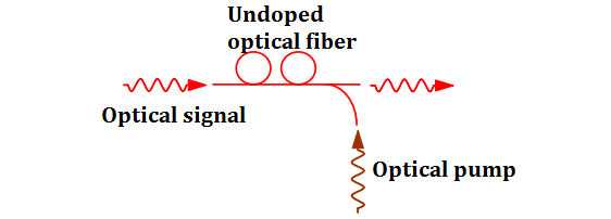
A-fiber-Raman-amplifier

Figure 5: A fiber Raman amplifier

In a Raman amplifier, the signal is amplified due to stimulated Raman scattering (SRS). Raman scattering is a process in which light is scattered by molecules from a lower wavelength to a higher wavelength. SRS is a nonlinear interaction between the signal and the pump and can take place within any optical fiber. In most fibers however the efficiency of the SRS process is low, high pump power (typically over 1 W) is required to obtain useful signal gain. Thus, in most cases Raman amplifiers cannot compete effectively with EDFAs. On the other hand, Raman amplification provides two unique advantages over other amplification technologies. The first advantage is that the amplification wavelength band of the Raman amplifier can be tailored by changing the pump wavelengths, and thus amplification can be achieved at wavelengths without being supported by competing technologies. The second, more important, advantage is that amplification can be achieved within the transmission fiber itself, enabling what is known as distributed Raman amplification (DRA). In this process high pump power is launched into the transmission fiber in order to provide amplification for the signal as it travels along the fiber. Since gain occurs along the transmission fiber, DRA prevents the signal from being attenuated to very low powers. Raman amplifiers are often used together with EDFAs to offer ultra-low NF combined amplifiers, which are useful in applications such as long links without inline amplifiers, ultra-long links expanding thousands of kilometers, or very high bit-rate links.

4.Conclusion
Optical amplifiers are  the critical technology for the optical communication networks, enabling the transmission of many terabits of data over distances from a few hundred kilometers and up to thousands of kilometers by overcoming the fiber loss limitation. Through concretely introducing optical amplifiers above, I hope this passage can help you get better understanding of optical amplifiers.