Which One to Choose? Fiber or Copper Patch Panel?

It seems that you haven’t figured out what a patch panel is. A patch panel is a mounted hardware assembly that contains ports used to connect and manage fiber or copper optic cables going in and out. Patch panels are also known as patch bays, patch fields or jack fields which are usually installed on enclosures or racks to simplify connections. If it breaks down, the entire system may fail. Patch panels can be assorted based on the number of ports they contain. They can be used in fiber and copper cabling systems. Here we have fiber and copper patch panels.

Fiber vs. Copper Patch Panel

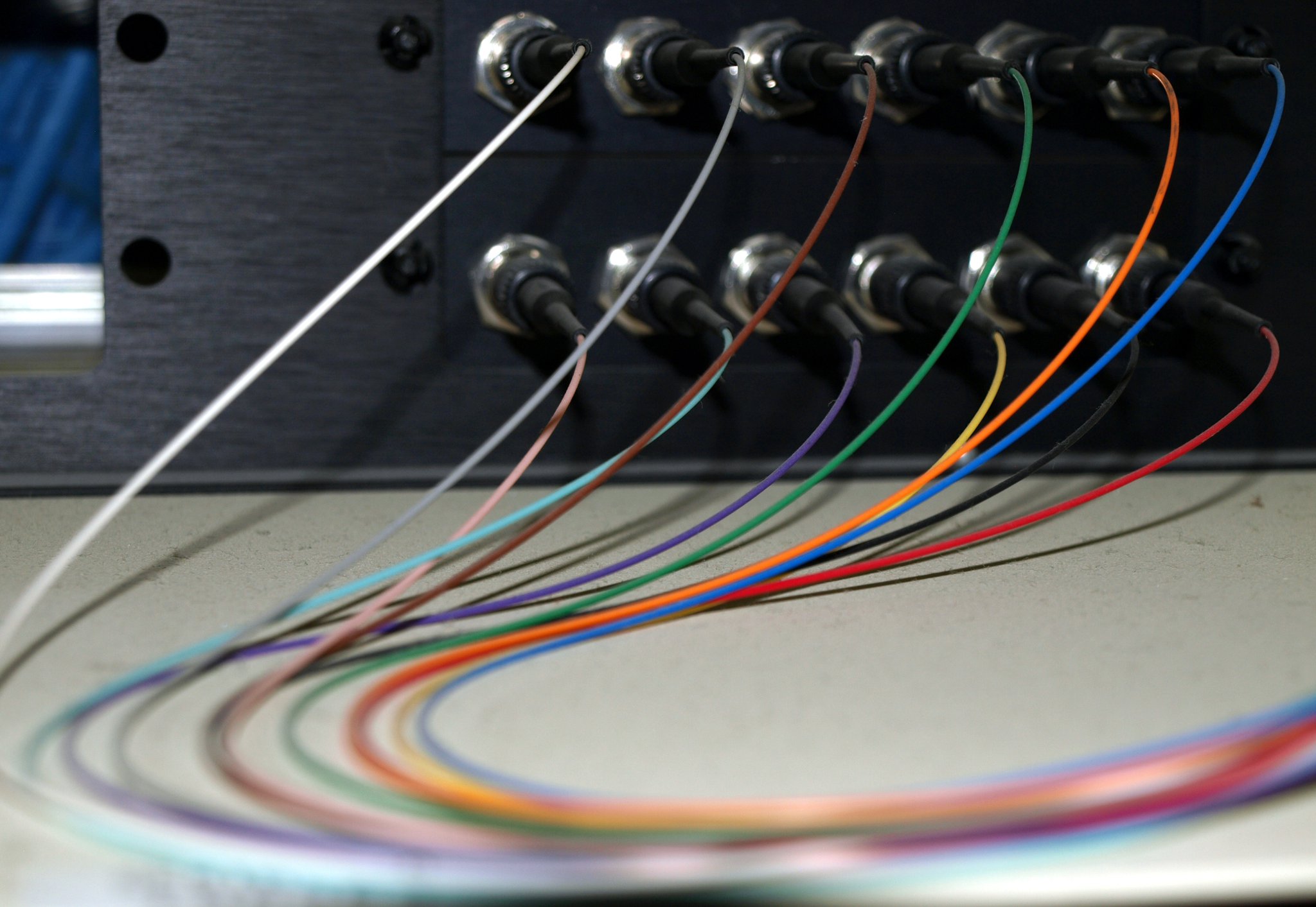
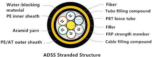
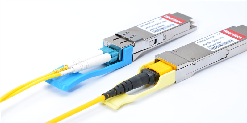
Fiber patch panels require two ports for a pair of wires. One port is responsible for the transmitting end while the other looks after the receiving end. The fact that fiber patch panels tend to be faster than copper does not make sense in the condition where the main function of a patch panel is to direct signal traffic, not to send the signal at a particular speed. When installing the panel, a fiber optical cable needs to be split at one end in order to gain access to the individual fibers. The separated fibers are fed into different ports, each of which has a fiber optical adapter. These adapters can then be used to plug individual fibers into other devices. The loss caused by interface may be noticeable. Besides, if the fiber interface doesn’t connect perfectly, you may not get it work successfully.

Copper patch panels have the 110-insulation displacement connector style on one side and 8-pin modular ports on the other. Wires coming into the panel are therefore terminated to the insulation displacement connector. On the opposite side, the 8-pin modular connector plugs into the port which corresponds to the terminated wires. With the copper patch panel, each pair of wires has an independent port. And when the front copper touches the copper in the back, a little bit of the signal is lost but not enough to worry about. And copper is easy to interface- even if the connector doesn’t match perfectly, as long as wire A touches wire B, you get a connection.

Fiber and Copper Patch Panels Provided by FS.COM

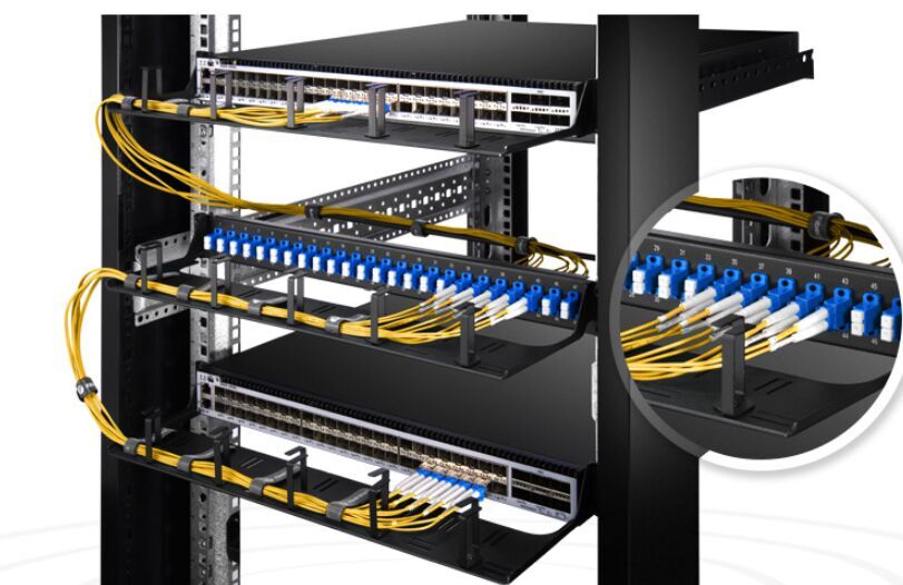
1U High 19″ fiber patch panel is easy to install for better deployment and expand your network for interconnection and cross-connection inside the rack mount and cabinet. It has 24 ports and is available with two adapter types: SC and LC duplex.

fiber patch panel

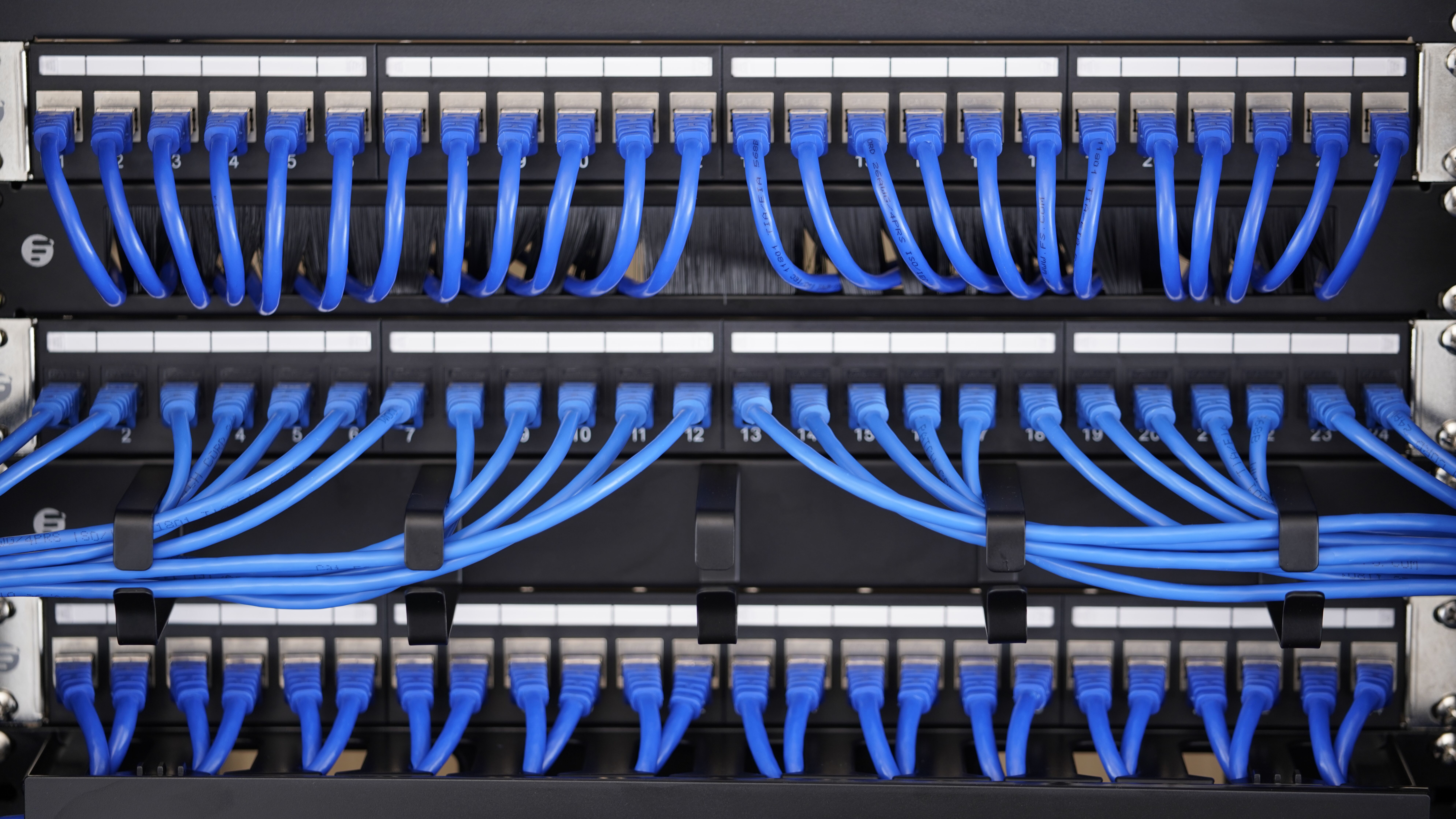
Cat6 patch panels deliver a steady 250 MHz connection to copper Gigabit switches, ideal for Ethernet, Fast Ethernet and Copper Gigabit Ethernet (1000Base-T) network applications. They are available in 6-port and 8-port module groupings, in 8, 12, 24, and 48-port sizes. The cat6 patch panel provided by FS.COM contains user-friendly number coding and removable rear cable manager which is conducive to uninstall and install. Ordered number coding enables it easy to install and distinct cable. In addition, management bar and numbers are easy for cabling neat, organized and connection identification.

copper patch panel

Conclusion

It is not easy to tell which fiber patch panel is better unless in a given situation. The copper and fiber patch panel both have their own advantages and shortcomings when applied to different systems. FS.COM also provides many kinds of patch panels, each representing a cost-effective solution for your application. And they can adapt to your changes and adds on the equipment.

Breakout or Distribution Cables — Which One to Choose?

Cables with multiple fibers are widely applied to high-density indoor or outdoor installations. Breakout and distribution fiber optic cables are the commonly used types. However, people may mix them together because they have a similar outer appearance. Actually, the inner structure of these cables is totally different. In this article, some differences between breakout cables and distribution cables will be discussed.

Structure of Breakout Cables and Distribution Cables

Breakout Cables Structure

The breakout cable is also known as fan-out cable. As the following picture shows, breakout cable consists of two or more simplex cables bundled around a central strength member. Each fiber has its own jacket and all of the fibers are packaged together inside the same outer jacket. Thus, breakout cable can also be broken out into individual simplex cables for separate use when running through walls of a building. The breakout cable is usually designed with tight buffer and the fiber counts are varied from 2 to 24 fibers.

breakout cables structure

Distribution Cable Structure

Unlike the breakout cable, distribution cable is smaller in size and lighter in weight. Fiber counts of distribution cable can be more intensive than the breakout cable for up to 144 fibers. Many fibers may not be used immediately but can be left for future expansion. Although the distribution cable has a more compact design, the tight-buffered fibers inside the cable are only bundled in a single outer jacket for protection, as shown in the picture below. Yet this has made the distribution fiber optic cable to be easily handled and stripped for field termination.

distribution fiber cable structure

Cable Types

Types of Breakout Cables

According to different fiber ratings, breakout cable can be divided into breakout riser cable and breakout plenum cable. Breakout riser cable is widely used for vertical riser and general horizontal applications. However, when the cable is needed for ducts, plenums and other spaces with environmental air returns, breakout plenum cable is the better choice.

breakout cable

Types of Distribution Cable

Likewise, distribution cable also has the riser and plenum cable types for riser and plenum spaces deployment. Apart from these types, distribution cable is sometimes equipped with the armored jacket for a stronger protection. Armored distribution riser or plenum cable can be applied to harsh premise environments where heavy-duty protection is required.

distribution cable

Cable Applications
Breakout Cable Applications

Breakout cables may end up in communication closets, and users can manually change connections. It is also available to be used for direct connection to the device. Moreover, breakout cable is suitable for short riser or plenum areas and conduit runs, where a very simple cable run is planned to avoid the use of splice box or spliced fiber pigtails. Since breakout cable has a stronger design, it is ideal for industrial applications where ruggedness is needed.

Distribution Cable Applications

Distribution cable is typically used for fast installation and easy termination of outdoor and indoor applications. It supports high performance networks and its single-unit fiber design saves much space. Distribution cable usually ends up at patch panels or communication closets, where they are connected with devices for communications between separate offices or locations. Distribution cable is also used within buildings to provide high-density connectivity for applications of intra-building backbones, routing between telecommunications rooms and connected cables in riser and plenum environments.

Conclusion

In summary, it is a convenient solution to use breakout cables or distribution cables for multi-fiber applications. Certainly, when you have to make a choice between them, you also need to consider the price factor. Breakout cable is generally stronger and larger than the distribution cable, thus the cost will be more expensive. Be sure to have a second thought before making the decision.

Related Articles:
High-Density 40G to 10G Breakout Cabling Solutions
Tight-Buffered Fiber Distribution Cable for Indoor and Outdoor Use

Importance of Using Fiber Color Codes in Data Center

The utilization of fiber color code in data center effectively helps technicians make better cable management and reduce human errors. Without redundant checking process, people can easily get the information of the device by only one look. Making good use of the color code system can surely save much time during work. This article will mainly present the widely accepted color code system and its important functions.

fiber color code

Introduction to Fiber Color Code Systems

Fibers, tubes and ribbons in fiber optic cables are usually marked with different color codes to facilitate identification. There are many color code systems for national or international use. All these systems are characterized by using 12 different colors to identify fibers that are grouped together in a common bundle such as a tube, ribbon, yarn wrapped bundle or other types of bundle.

Different color code standards may be used in different regions. For example, the S12 standard is used for micro cables and nano cables in Sweden and other countries. The Type E standard is defined by Televerket and Ericsson used in Sweden. The FIN2012 standard is used in Finland, etc. However, there is one color code system widely recognized in the world, namely the TIA/EIA-598 standard.

Specifications of TIA/EIA-598 Color Codes

The following picture gives the fiber color coding of TIA/EIA-598 standard. If more than 12 fibers or tubes are to be separated, the color sequence is normally repeated with ring marks or lines on the colored fibers and tubes. As for the fiber cable jacket, orange, yellow, aqua and black color codes are used for their distinction.

color-code-system

Functions of Fiber Color Code in Data Center
Distinguishing Fiber Grades

As mentioned above, the outer jacket color codes are able to identify the fiber grades. OM1/OM2 cables often adopt the orange jacket, OM3/OM4 cables with aqua jacket, single-mode cables with yellow jacket and hybrid cables (indoor/outdoor cables and outside plant cables) with black jacket. One thing to note is that the mix of OM1 and OM2 or OM3 and OM4 cables may be troublesome. You should make sure not to mingle these cables with the same color code.

Identifying Fiber Patch Cords

Using fiber color code to label fiber patch cords can reduce the potential for human error. For instance, you may highlight mission-critical patch cords in red, and then teach all technicians that a red patch cord should only be moved with proper authorization or under supervision. Likewise, keeping the fiber connector color consistent with fiber grade color standards will make it simple for technicians to use the right connectors with the cables.

Separating Different Ports

The color-coded port icons can be helpful in identifying different network routings in accordance with internal needs. By tagging each patch panel port, you can simplify and streamline network management.

Differentiating Connector Boots

You can use fiber color code on connector boots to make routine maintenance and moves, adds and changes easier by helping technicians preserve correct parallel groupings for switch ports. If you change your connector color, you need to ensure that your fiber cable color represents the fiber grade to avoid confusion. You can also change the color of a connector boot to differentiate between different aspects of the network, making it easy for technicians to view the contrast within a panel.

Conclusion

Visual management is more intuitive for specialists to supervise the data center. Color code system has provided an ideal and easy way to solve the cabling problem. Inside the cables, the fiber buffers are also color-coded with standard colors to make connections and splices easier. Therefore, if you are still bothered by these issues of fiber patch cables, using the fiber color code system is a good way to go.

Related Articles:
How to Identify the Color Codes?
Fiber Patch Panel Color Codes

Things You Need to Know About ADSS Fiber Cables

When it comes to OSP (outside plant) deployment, many types of fiber optic cables are used for different OSP applications. ADSS (all-dielectric self-supporting) cable is the type that is strong enough to support itself between structures without using conductive metal elements. It is often installed along aerial transmission lines to be a communication medium for electrical utility companies. Both single-mode and multimode fiber can be arranged in ADSS cables. And when using single-mode fibers, the cable can carry the maximum of 144 fibers. But do you know the basic structures of ADSS fiber cable? What are the advantages of using ADSS cable? And how can you prevent ADSS cable from damage? This article will give you all the answers.

ADSS cable

Structures of ADSS Cable

There are generally two kinds of structures for ADSS cable. One is called as central tube structure. From the following picture, the fiber of a certain length is placed in a PBT loose tube filled with water-blocking material. Then it is wrapped with aramid yarn according to the desired tensile strength and extruded with PE or AT sheath. This structure has a smaller diameter and lighter weight. But the fiber length is limited.

adss-central-tube-structure

The other type of structure is called as stranded structure. The following picture shows that the fiber loose tubes are surrounding around a central strength member (usually as FRP material). And the rest parts are similar to the central tube structure. This type is able to obtain a longer fiber length. Although the diameter and weight are relatively big, it is better to be deployed for large span applications.

adss-stranded-structure

Benefits of ADSS Cable

There are many advantages of using ADSS fiber cable. The overall weight and diameter of the cable are small which is a relief to the towers and poles. And its total transmission range is large enough to reach up to 1200 meters. Using the polyethylene sheath will also protect the cable from corrosive effect. ADSS cable’s non-metallic structure makes it possible to be anti-lightning. And the aramid yarn helps the cable to have good tensile performance and temperature performance under extreme weathers. The maximum lifespan of ADSS fiber cables can even reach up to thirty years.

Precautions for ADSS Cable Damage

  • Point 1, since many cables are running through mountainous areas, it is inevitable that the cables will be scratched or bent when come across trees or rocks. Especially for the cable sheath damage, it will greatly harm the service life of cable because the surface can be corroded once exposed to the dust and salty environment. Thus, the cable installation should be under careful examination and monitoring.
  • Point 2, due to the partial force during the line construction, common accidents like broken fiber and high loss point can be occurred. Lots of people think it is the problem of cable quality, but actually, it is because of the wrong construction process. Therefore, taking control of the constant tension at a uniform speed during installation is very important.
  • Point 3, another common damage is the broken fiber at strain towers. This is because of the wrong operation or partial force on fibers. During the construction, installers must pay attention to the proper angle and pulling direction of fibers to avoid such accidents.

Conclusion

ADSS cable is ideal for installation in distribution as well as transmission environments. It does not need support or messenger wire, a single pass is sufficient for installation which makes it a cost-effective and simple way of setting up fiber optic networks. With careful installation, this type of fiber optic cable can bring much convenience for the proper application.

Related Articles:

How to Reduce Various Types of Losses in Optical Fiber?

Types of outdoor fiber optic cable

Choose the Right Patch Cable for Your Transceiver Module

To a large extent, a fluent data transmission relies on the seamless transition between patch cables and fiber optic transceivers. As high bandwidth gradually dominates the market, patch cables and transceivers become much more essential to data transmission, especially for data transmission between the switches and equipment. But when you try to find the right patch cable for your transceiver, you may feel dazzling about the great variety of products. Don’t worry, this article will help you find the quickest way to choose the suitable product. But first, let’s have a look at the basic knowledge about patch cables and transceiver modules.

Overview of Patch Cables and Transceiver Modules

A patch cable or patch cord is an electrical or optical cable used to connect one electronic or optical device to another for signal routing. It is composed of an electrical or optic cable terminated with connectors on the ends. Optical patch cables are now widely used in data centers for data transmission. They have different fiber connectors including LC, SC, ST, FC, MTRJ, E2000, MU, MPO/MTP, etc. As for fiber types, there are also single-mode patch cables and multimode patch cables. Single-mode patch cables can further be classified into OS1 and OS2. While the multimode can be further divided into OM1, OM2, OM3 and OM4.

fiber-vs.-copper

Transceiver is a self-contained component that can both transmit and receive. It is often inserted in devices such as switches, routers or network interface cards which provide one or more transceiver module slot. Many transceivers types, such as SFP, X2, XENPAK, XFP, SFP+, QSFP+, CFP, etc. are used for various applications. The transceiver accepts digital signals from the Ethernet device and converts them to optical signals for transmission over the fiber.

Several Aspects to Consider
Transmission Media

Two kinds of transmission media can be found in the network. They are optic fiber cable and copper cable. Therefore, transceivers also have two types based on transmission media — copper based transceivers and fiber optic based transceivers. Copper based transceivers like 100BASE-T SFP, 1000BASE-T SFP are the commonly used types. They have a RJ45 interface to connect with the copper cables. Generally, cat 5, cat 6 and cat 7 cables attached with RJ45 connectors are typically linked to the copper based transceivers.

Compared with copper based transceivers, fiber optic transceivers support higher data rates for over 100 Gbps. The supported fiber patch cables are more complicated for selection. Usually single-mode and multimode fiber patch cables are used. But according to different transmission rates and transmission distance, further choices should be made.

Transmission Rate and Distance

It is known that data rate decreases as the transmission distance increases in fiber optic cables. Multimode fiber optic cables are often used for short distances due to the high cost of single-mode optical cables. But single-mode patch cables have better performance for different data rates in both long and short distances. Thus, if your transceiver supports high data rate over long distance, single-mode should be a better choice, and vice versa.

Transceiver Interface

Interfaces are also important to the selection of patch cables that match with transceivers. Optical transceivers usually use one port for transmitting and one port for receiving. Cables with duplex SC or LC connectors are typically employed to connect with this type of fiber optic transceivers. However, for BiDi transceivers only one port is used for both transmitting and receiving. Thus, simplex patch cables are used with BiDi transceivers.

Other high data rate transceivers like 40G/100GBASE QSFP+ often use MTP/MPO interfaces. They should be connected to the network with multi-fiber patch cords attached with MTP/MPO connectors. If these ports are used for 40 G to 10 G or 100 G to 10 G connections, fanout patch cables should be used.

transceiver-and-patch-cords

Conclusion

Knowing the transmission media, transmission data rate and distance, transceiver interfaces can give you a general direction of which type of patch cables should be chosen. Only matched patch cables and transceiver modules can provide better performance.