Power over Ethernet (PoE) technology, which combines power and data transmission together over a single cable, has made great advances over the last decades. Applications for PoE have extended from the VoIP phone and security camera to IoT devices including medical devices, access control systems for intelligent buildings, etc. Every evolution in PoE technology has witnessed the transition to higher power level, however, the overheating issue along with higher power in PoE cabling becomes an essential issue. This post will discuss the heat rise with high power PoE as well as exploring solutions to avoid overheating problems.
Evolution of PoE Standards
As the PoE market continues to grow, PoE standards go through several generations of versions from the primary IEEE 802.3af standard to the latest IEEE 802.3bt standard to accommodate the market needs. In the following chart, we will take a closer look at the four PoE standard types.
| Type 1 | Type 2 | Type 3 | Type 4 | |
|---|---|---|---|---|
| Name | PoE | PoE+ | PoE++, UPoE | High-Power PoE |
| Name | PoE | PoE+ | PoE++, UPoE | High-Power PoE |
| PoE Standard | IEEE 802.3af | IEEE 802.3at | IEEE 802.3bt | IEEE 802.3bt |
| Max. Power per Port | 15.4 W | 30 W | 60 W | 100 W |
| Power to PD | 12.95 W | 25.5 W | 51 W | 71.3 W |
| Twisted Pair Used | 2-Pair | 2-Pair | 4-Pair | 4-Pair |
| Supported Cables | Cat5e | Cat5e | Cat5e | Cat5e |
| Typical Application | IP phone | Video phone | MGMT device | LED lighting |
The PoE standard IEEE 802.3af, also called PoE type 1 is an early standard designed for the low power needed devices such as traditional IP phones and the security camera. Nevertheless, with the appliance of high power devices, 12.95W is not enough for their needs, which hence becomes a limitation of PoE. Later, the early standard was followed by the IEEE 802.3at which expanded the range of PoE applications such as video telephone and dual-band desktop access, and then came the latest IEEE 802.3bt standard. Along with the increased PoE power level, it causes a temperature rise within a PoE cable. Especially when the PoE power output reaches as high as 100 W, the heat rise of PoE cable will become more obvious.
Heat Rise—The Concern Emerging With High Power PoE
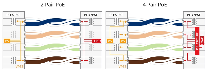
In the previous IEEE 802.3af and IEEE 802.3at PoE standards, the maximum power provided by PSE is 15.4W and 30W accordingly. It is not likely to overheat at this level of power unless under extreme ambient temperatures or cable bundles are too large. Two pairs of the four pairs in an Ethernet cable is enough to carry the current. However, as the power to the end devices is increasing, PoE cabling is bound to improve to deliver higher power. The effective means to improve the cable efficiency is to increase the number of wires carrying the power—Type 3 and type 4 PoE standard uses all four pairs to inject power rather than 2 pairs used in the early standards.
Figure 1: 2-pair PoE vs 4-pair PoE
The 4-pair PoE doubled the amount of available power, enabling PoE expanding to support higher-powered devices instead of being limited to the devices needing low power such as 15W or 30W. However, high power is not the only thing requiring attention in PoE cabling. Heat rise is another one. Manufacturers and technical consortiums have worked to evaluate the thermal impact of delivering 100 Watts of power over 4-pair PoE. Apparently the increasing power increases current flow, which significantly results in an increase in cable heating.
Why Is Heat Rise a Key Issue?
Why do we consider heat rise in PoE cabling so seriously? It is all because of the negative effects of heat rise on the link stability, and cabling lifespan.
Overheat in PoE cabling can result in an increase in insertion loss. To maintain the signal quality, administrators have to shorten the cable length to compensate for the loss in the link. Heat rise will lead to the premature aging of jacketing materials. If operated under the high-temperature circumstances for a long time, the outer jacket may get broken and impact the inner construction, breaking the balance of the twisted pair cable and causing the decline of electric performance. Furthermore, since the influence of heat rise in high power PoE is irresistible, careful evaluation before the PoE cabling deployment is required in the event of subsequent disposal. Better cabling cool will help to reap the benefit of excellent transmission performance.
Common Types of High Power PoE Applications
As has been mentioned in the front section, heat rise occurs with high power PoE cabling. Driven by the need for higher power all around the world, new PoE technology is expected to progress to enable new PoE markets and widen PoE’s scope to the existing markets requiring high power. Applications that take advantage of high power PoE technology include:
- Intelligent buildings with enterprise IoT (connected LED lighting)
- Safe cities (high definition pan-tilt-zoom security cameras)
- Retail POS systems and digital signage
- High-performance wireless access points
- Kiosks
- Small cells
Precautions to Minimize Heat Rise in PoE Cabling
Ultimately, the overheating problem can be attributed to the cable/conductor construction and specific installation situations. The following suggestion to minimize heat rise in PoE cabling will be listed from these aspects in an exhaustive way.
1. Use higher category cabling
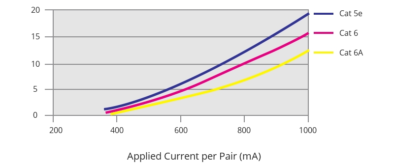
In general, the higher the cable category is, the lower the heat will rise. According to the testing results from Leviton engineers, the higher category cabling correlated with lower amounts of temperatures after they tested several different category types of fiber cables. For new PoE installations, TIA suggests Cat6A for use.
Figure 2: Current per category cable
2. Select cabling with a larger conductor (i.e., lower gauge number)
Heat rise can be the result of the conductor resistance in PoE applications. The larger the conductor is, the more it can reduce conductor resistance, the easier current flow it will allow for and the less heat it will generate.
3. Cable connectors should feature a solid metal body
Consider using connectors with an all-metal-body construction, instead of plastic. Compared with thermoplastic jacketing materials, mental has a higher conductivity and does better in heat dissipation.
4. Choose cables with smaller bundle size
By measuring the temperature of a large cable bundle and the smaller bundles separated from the big one, TIA identified that the core of the large cable bundle experienced higher temperature in comparison to smaller bundles. TSB-184-A developed by the TIA subcommittee recommended leaving cables unbundled to facilitate better heat dissipation. If not possible, smaller bundle sizes are recommended.
5. Install shielded cabling
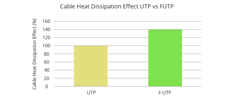
It has been affirmed that the existence of a metallic shield or foil helps dissipate heat. If the cable utilizes a foil shield around each pair, it will deliver better heat-dissipating qualities than the unshielded twisted pair cables. Therefore, S/FTP or F/UTP cables are more applicable than UTP cabling systems in PoE applications.

Figure 3: Cable heat dissipation effect UTP vs F/UTP
6. Plan your PoE cable management
Group your cables as loosely as possible instead of bundling all of them as a whole. Distribute your cable or cable bundles as dispersed as possible in an available area. High cable density will contribute to more heat within the cable or cable bundles. You are suggested to use cable management tools that allow for better airflow around cables and cable bundles.
Related Articles:
How to Lower Cabling Temperature for PoE?
Powering PoE Switch From A PoE Switch: Is It Possible?
Article Source: How to Avoid Overheating in PoE Cabling?


