How to Add CWDM MUX/DEMUX System to Your Network?

Coarse wavelength division multiplexing (CWDM) technology is developed to expand the capacity of a fiber optic network without requiring additional fiber. In a CWDM system, CWDM Mux/Demux (multiplexer/demultiplexer) is the most important component. Usually, a CWDM Mux/Demux is used to increase the current fiber cable capacity by transmitting multiple wavelengths, typically up to 18 separate signals over one fiber. This article may mainly describe what is Mux in networking and how to install your CWDM Mux/Demux system. Unless you are an experienced user, we recommend that you follow the detailed installation steps described in the rest of this article.

Introduction to CWDM MUX/DEMUX Module

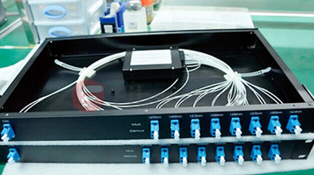
CWDM Mux/Demux module is a passive device, very reliable and simple to use. These devices are available with a variety of wavelength combinations, usually from 1270nm to 1610nm (20nm spacing). Based on different applications, a CWDM Mux/Demux module can be designed into different channels. A typical 4 channel Mux/Demux module will be used to multiplex four different wavelengths onto one fiber (shown in the picture below). This allows you to simultaneously transmit four different data over the same fiber. If you are using a CWDM multiplexer at the beginning of your network, you will use a CWDM demultiplexer at the opposite end to separate or demultiplex the wavelengths to allow them to be directed to the correct receivers. Usually, a CWDM Mux/Demux is a module that can be used as a multiplexer or demultiplexer at either end of the fiber cable span. However, it must still be used in pairs.

What IS MUX in Networking?

What is MUX in networking? A basic CWDM Mux/Demux system comprises a Local unit, the CWDM Mux/Demux module and a Remote unit. Usually, a Local or Remote unit refers to two different switches. In general, to install a CWDM Mux/Demux module, a chassis should be installed first to hold the module. Besides, to connect a CWDM Mux/Demux module to a switch, we should install CWDM SFP transceivers in the switch first. Then using the single mode patch cables to connect the transceivers to the CWDM Mux/Demux module. Therefore, when we want to build a CWDM Mux/Demux system, the components we need usually include rack-mount chassis, CWDM Mux/Demux module, CWDM SFP transceiver and single mode patch cables (shown in the table below).

Part Name Product Photo Description
Rack-mount Chassis 2-Slot Chassis Customized Empty  Rack Chassis to hold 2/3/4/12 Pieces custom small size LGX Cassette
CWDM Mux/Demux CWDM Mux & Demux 2/4/5/8/9/16/18 Channels CWDM MUX DEMUX 1270nm to 1610nm with Monitor Port
CWDM SFP Transceiver CWDM SFP 1.25Gbps CWDM SFP 1270nm to 1610nm 20/40/80/100/120km Transceiver
Singlemode Fiber Cables singlemode patch cable LC to LC 9/125 Simplex/Duplex Single-mode Fiber Patch Cable

How to Add CWDM MUX/DEMUX System to Your Network?

After knowing what is MUX in networking? Next, we’ll learn how to install a CWDM Mux/Demux system, there are four basic steps:

  • Install the Rack-Mount Chassis

The CWDM rack-mount chassis can be mounted in a standard 19-inch cabinet or rack. When to attach the chassis to a standard 19-inch rack, ensure that you install the rack-mount chassis in the same rack or an adjacent rack to your system so that you can connect all the cables between your CWDM Mux/Demux modules and the CWDM SFP transceivers in your system.

  • Install the CWDM Mux/Demux Modules

To insert a module, you should align the module with the chassis shelf (shown in the figure below) first and then gently push the module into the shelf cavity. Finally, tighten the captive screws.

  • Connect the CWDM Mux/Demux to Switch

After inserting the CWDM SFP transceiver into the switch, then we should use the single mode patch cable to connect the transceiver to the CWDM Mux/Demux.

Please mind that CWDM Mux/Demux pairs must carry transceivers with the same wavelength. Because each transceiver will work only at the appropriate port and the data will always flow between devices with the same wavelengths. CWDM SFP transceivers with different wavelength may have a different color code. Use the CWDM SFP transceiver color codes shown in the picture below to help you connect the CWDM Mux/Demux to your system.

  • Connect the CWDM MUX/DEMUX Pairs

Once you use a CWDM multiplexer on one end of your networks, you must use a demultiplexer on the other end of the networks. Therefore, the last step to complete CWDM Mux/Demux system is to connect the Mux/Demux pairs (or multiplexer and demultiplexer). For duplex Mux/Demux, a pair of single mode patch cables must be used. For simplex Mux/Demux, only one single mode patch cable is enough. After all done, your CWDM Mux/Demux system is then installed successfully.

Conclusion

What is MUX in networking? In summary, Mux/Demux system is a cost-effective solution which is easy to install. CWDM Mux/Demux, CWDM multiplexer only, and CWDM demultiplexer only are a flexible, low-cost solution that enables the expansion of existing fiber capacity and let operators make full of use of available fiber bandwidth in local loop and enterprise architectures. Fiberstore CWDM Mux/Demux is a universal device capable of multiplex multiple CWDM (1270~1610nm) up to 18 channels (2, 4, 5, 8, 9, 16, 18 channels are available) or optical signals into a fiber pair or single fiber. Together with our CWDM transceivers or the wavelength converters, the bandwidth of the fiber can be utilized in a cost-effective way.

The WDM System

Introduction
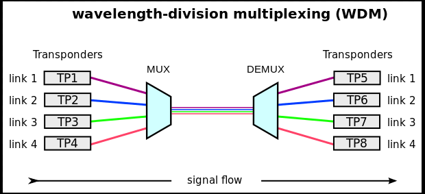
In fiber-optic communications, wavelength-division multiplexing (WDM) is a technology which multiplexes a number of optical carrier signals into a single optical fiber by using different wavelengths of laser light. This technique enables bidirectional communications over one strand of fiber, as well as multiplication of capacity. A WDM system (Figure 1) uses a multiplexer at the transmitter to join the signals together, and a demultiplexer at the receiver to split them apart. With the right type of fiber it is possible to have a device that does both simultaneously, and can function as an optical add-drop multiplexer. The concept was first published in 1978, and by 1980 WDM systems were being realized in the laboratory. As a system concept, the ways of WDM includes coarse wavelength-division multiplexing (CWDM) and dense wavelength-division multiplexing (DWDM).

20150417100422

Figure 1: The WDM system

The CWDM System
In simple terms, CWDM equipment performs two functions: segregating the light to ensure only the desired combination of wavelengths are used, multiplexing and demultiplexing the signal across a single fiber link.

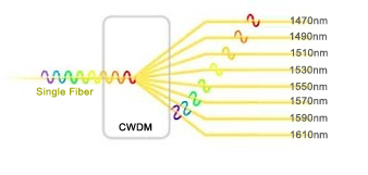
Typically CWDM solutions provide 8 wavelengths capability, separated by 20nm, from 1470nm to 1610nm, enabling the transport of 8 client interfaces over the same fiber, as is shown in Figure 2. What’s more, CWDM has the capability to transport up to 16 channels (wavelengths) in the spectrum grid from 1270nm to 1610nm with a 20nm channel spacing. Each channel can operate at either 2.5, 4 or 10Gbit/s. CWDM can not be amplified as most of the channels are outside the operating window of the erbium doped fiber amplifier (EDFA) used in Dense Wavelength Division Multiplexing (DWDM) systems. This results in a shorter overall system reach of approximately 100 kilometers. However, due to the broader channel spacing in CWDM, cheaper un-cooled lasers are used, giving a cost advantage over DWDM systems.

20150417100626

Figure 2:The CWDM system

CWDM proves to be the initial entry point for many organizations due to its lower cost. Each CWDM wavelength typically supports up to 2.5Gbps and can be expanded to 10Gbps support. This transfer rate is sufficient to support GbE, Fast Ethernet or 1/2/4/8/10GFC, STM-1/STM-4/STM-16/OC3/OC12/OC48, as well as other protocols.

CWDM is the technology of choice for cost efficiently transporting large amounts of data traffic in telecoms or enterprise networks. Optical networking and especially the use of CWDM technology has proven to be the most cost efficient way of addressing this requirement.

In CWDM applications, a fiber pair (separate transmit and receive) is typically used to serve multiple users by assigning a specific wavelength to each subscriber. The process begins at the head end (HE) or hub, or central office (CO), where individual signals at discrete wavelengths are multiplexed, or combined, onto one fiber for downstream transmission. The multiplexing function is accomplished by means of a passive CWDM multiplexer (Mux) module employing a sequence of wavelength-specific filters. The filters are connected in series to combine the various specific wavelengths onto a single fiber for transmission to the field. In the outside plant a CWDM demultiplexer (Demux) module, essentially a mirror of the Mux, is employed to pull off each specific wavelength from the feeder fiber for distribution to individual FTTX applications.

CWDM is suitable for use in metropolitan applications, also being used in cable television networks, where different wavelengths are used for the downstream and upstream signals. In these systems, the wavelengths used are often widely separated, for example, the downstream signal might be at 1310 nm while the upstream signal is at 1550nm. CWDM can also be used in conjunction with a fiber switch and network interface device to combine multiple fiber lines from the switch over one fiber. CWDM is optimized for a cost conscience budgets in mind, with low-cost, small-powered laser transmitters enabling deployments to closely match guaranteed revenue streams.

The DWDM System
DWDM stands for Dense Wavelength Division Multiplexing. Here “dense” means the wavelength channels are very narrow and close to each other. DWDM uses the same transmission window but with denser channel spacing. Channel plans vary, but a typical system would use 40 channels at 100 GHz spacing or 80 channels with 50 GHz spacing.

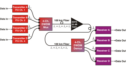
DWDM works by combining and transmitting multiple signals simultaneously at different wavelengths on the same fiber, as is shown in Figure 3. In effect, one fiber is transformed into multiple virtual fibers. So, if you were to multiplex eight OC -48 signals into one fiber, you would increase the carrying capacity of that fiber from 2.5 Gb/s to 20 Gb/s. Currently, because of DWDM, single fibers have been able to transmit data at speeds up to 400Gb/s.

20150417100955

Figure 3: The DWDM system

A basic DWDM system contains five main components: a DWDM terminal multiplexer, an intermediate line repeater, an optical add-drop multiplexer (OADM), a DWDM terminal demultiplexer and an Optical Supervisory Channel (OSC). A DWDM terminal multiplexer contains a wavelength-converting transponder for each data signal, an optical multiplexer and an optical amplifier (EDFA). An intermediate line repeater is placed approximately every 80–100 km to compensate for the loss of optical power as the signal travels along the fiber. An optical add-drop multiplexer is a remote amplification site that amplifies the multi-wavelength signal that may have traversed up to 140 km or more before reaching the remote site. A DWDM terminal demultiplexer consisting of an optical demultiplexer and one or more wavelength-converting transponders separates the multi-wavelength optical signal back into individual data signals and outputs them on separate fibers for client-layer systems (such as SONET/SDH). An Optical Supervisory Channel (OSC) is a data channel which uses an additional wavelength usually outside the EDFA amplification band (at 1,510nm, 1,620nm, 1,310nm or another proprietary wavelength).

DWDM is designed for long-haul transmission where wavelengths are packed tightly together and do not suffer the effects of dispersion and attenuation. When boosted by erbium doped fiber amplifiers (EDFAs)—a sort of performance enhancer for high-speed communications—these systems can work over thousands of kilometers. DWDM is widely used for the 1550nm band so as to leverage the capabilities of EDFA. EDFAs are commonly used for the 1525nm ~ 1565nm (C band) and 1570nm ~ 1610nm (L Band).

A key advantage to DWDM is that it’s protocol and bit rate independence. DWDM-based networks can transmit data in IP, ATM, SONET/SDH, and Ethernet, and handle bit rates between 100Mb/s and 2.5Gb/s. Therefore, DWDM-based networks can carry different types of traffic at different speeds over an optical channel. From a QOS standpoint, DWDM-based networks create a lower cost way to quickly respond to customers’ bandwidth demands and protocol changes.

Conclusion
WDM, as a multiplexing technology in optical field, can form a optic-layer network called “all-optic network”, which will be the most advanced level of optical communications. It will be the future trend of optical communications to build a optical network layer based on WDM and OXC to eliminate the bottleneck of photoelectric conversion with a pure all-optic network. As the first and most important step of all-optic network communications, the application and practice of WDM is very advantageous to developing the all-optic network and pushing forward optical communications!

Some Structions of CWDM From Fiberstore

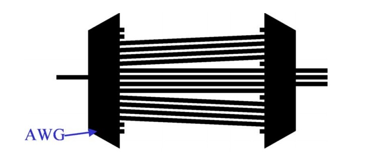
We all know that there is a type of WDM called CWDM, which has a 20 nm channel spacing. And the channel spacing is so wide because it is designed for non temperature controlled laser transmitters. The passbands for CWDM typically must be wide and flat with a bandwidth greater than 14 nm. The band multiplexer is a good way to make a CWDM de/multiplexer. The Figure show me that a waveguide a layout for an 8 channel cwdm multiplexer and the measured response. Because the channel spacing is so wide, the AWG grating orders are vary small and having unequal path lengths in the AWL, adds a negligible amount of chromatic dispersion (allowing one to use a “U” shape for the AWL, making it more compact). Thus, the AWGs take on a “W” shape, and the AWL takes on a “U” shape. A highly compact silica waveguide PLC 4 channel CWDM multiplexer made using a completely different technique, a two dimensional reflective hologram.

awg

Transparent CWDM MUX/DEMUX EQUIPMENT is typically passive (not powered). Passive devices cannot generate or repeat optical signals. Additionally, IOAs operate in a small wavelength range that overlaps only three CWDM signals. Some CWDM signals are unaffected by IOAs, so each CWDM span must terminate at a distance determined by the unamplified signals. Therefore, no benefit is realized by amplifying any of the CWDM signals. This means that all optical signals loss introduces by CWDM mux/demux equipment, splices, connectors, and the fiber must be subtracted from the launch power of the colored GBIC/SFP installed in the client.

CWDM can be used by enterprise on leased dark fiber to increase capacity (for example, from 1Gbps to 8 Gbps or 16 Gbps) over metro area distance. One problem with CWDM is that the wavelengths are not compatible with erbium-doped fiber amplifier (EDFA) technology, which amplifies all light signals within their frequency range.

cwdm

As for the fiber optical amplifier, we have a wide range of it, such as EDFA optical amplifier Booster Amplifier, CATV amplifier, In-line Amplifier, Booster Amplifier, WDM amplifier and so on, want to know more knowledge of it, you can visit into Fiberstore’s tutorial. Related product you can vist Fiberstore’s home page, you must find what you want.

Let me introduce our company, Fiberstore. it designs, manufactures, and sells a broad range of optical communication products, including passive optical network, such as the passive cwdm mux or optical splitter used in the enterprise, access, and metropolitan segments of the market, In particular, Fiberstore products include optical subsystems used in fiber-to-the-premise, or FTTP, deployments which many telecommunication service providers are using to deliver video, voice, and data services.

Typical CWDM Optical Elements and Features

CWDM VS DWDM differ noticeably in the spacing between adjacent wavelengths. DWDM packs many channels into a small usable spectrum, spacing them 1 to 2 nm apart; DWDM systems support a high channel count, but also require expensive cooling equipment and independent lasers and modulators to ensure that adjacent channels do not interfere. CWDM systems, on the other hand, use 10 to 25 nm spacing, with 1300 or 850 nm lasers that drift less than 0.1 nm/c. This low drift eliminates the need for cooling equipment, which, in turn, reduces the total system cost. As a result, CWDM systems support less total bandwidth than DWDM systems, but with 8 to 16 channels, each operating between 155 Mbps and 3.125 Gbps to over 100 Gbps. Typical systems support eight wavelengths, data rates up to 2.5 Gbps per wavelength, and distances up to 50 km.

CWDM uses lasers with a wide channel CWDM wavelength spacing. In contrast, DWDM, which is widely used in long-haul networks and some metro core networks (particularly those with large diameters), uses lasers with much narrower wavelength spacing, typically 0.8 or 0.4 nm. The wide channel spacing of CWDM means a lower system cost can be achieved. This lower equipment cost is the result of a lower optical CWDM mux/demux cost (due to wider tolerance on the wavelength stability and bandwidth).

CWDM represents significant costs savings-from 25% to 50% at the component level over DWDM, both for equipment OEMs and service provides. CWDM products cost about 3500 dollars per wavelength. Traditional CWDM only scale to about eight wavelengths, but for metro access applications, this may be adaquare. Also, mux demux manufacturer china have found ways to combine CWDM with its regular DWDM blades that allow the systems to scale up to 20 wavelengths. CWDM system architecture can benefit the metro access market because it takes advantage of the inherent natural properties of the optical devices and eliminates the need to artificially control the component characteristics.

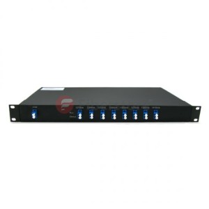
8 channels, 1RU Rack Mount, Duplex, CWDM Mux  Demux

The typical CWDM optical elements are as follows:

CWDM Uncooled Coaxial Lasers: Distributed-feedback multiquantum well (DFB/MQW) lasers are often used in CWDM systems. These lasers typically come in eight wavelengths and feature a 13 nm bandwidth. Wavelength drift is typically only 5 nm under normal office conditions (say, with a 50℃ total temperature delta), making temperature compensation unnecessary. For additional cost savings, the lasers do not require external gratings or other filters to achieve CWDM operation. They are available with or without an integral isolator.

CWDM Transmitters/Receives: OC-48 CWDM transmitters typically use an uncooled DFB laser diode and are pigtailed devices in a standard 24-pin DIP package. Six to eight channels are supported (six channels: 1510 to 1610 nm; two additional channels are located at 1470 and at 1490 nm.) The OC-48 receiver typically uses an APD photodetector, has a built-in DC-DC converter, and employs a PLL for clock recovery. Transmission distances of up to 50 km are achievable with these modules.

CWDM Multiplexers/Demultiplexer: These come in 4 or 8 channel module, just 4 channel CWDM Multiplexer or 8 channel CWDM Multiplexer, typically use thin -film filters optimized for CWDM applications, with filtering bands matched t other CWDM wavelengths. Filters need to feature low insertion loss and high isolation between adjacent channels.

CWDM Optical ADD/Drop Modules (OADMS): These are available in various configurations with one, two, or four add and drop channels using the same thin-film filters as the CWDM mux and demux modules.

Now Fiberstore is doing with 30% of the price discount of CWDM/DWDM products, and if you have interested in it, welcome to visit our online store.

The Advantage of CWDM in Metropolitan Area Network

Because of the rapid development of data services, the speed of network convergence is accelerating, MAN is becoming a focus of network construction, market competition pressure makes the telecom operators more sensitive to the cost of network. Aimed at the demand of the market, low-cost MAN CWDM products arises at the moment.

With full spectrum CWDM league (FCA) vigorously promote of CWDM Technology and ITU-T for the standardization of CWDM, it makes CWDM technology equipment manufacturers and operators be the focus of attention. The ITU-T 15th team through CWDM wavelength grid of standard G.694.2, and become a milestone in the history of the development of CWDM technology. The 15th team also puts forward the definition of CWDM system interface right app draft standard. Shanghai bell and other companies in China in the standardization of CWDM technology also has made certain contribution, relevant domestic standards are also under discussion.

As the the growth of the market demand and the standardization of CWDM technology rapidly, many communication equipment manufacturers such as Nortel, Ciena, Huawei, alcatel Shanghai bell (asb), fire network developed related products and gain a wide range of applications in the market.

CWDM system is a low cost WDM transmission technology towards MAN access layer. In principle, CWDM is using optical multiplexer to different wavelengths of light to reuse the signals to single fiber optic transmission, at the link of the receiving end, with the aid of photolysis of multiplex fiber mixed signal is decomposed into different wavelength signal, connected to the corresponding receiving equipment. And the main difference with DWDM is that: compared with the 0.2nm to 1.2 nm wavelength spacing in DWDM system, CWDM Wavelength Spacing is wider, wavelength spacing of 20 nm industry accepted standards. Each wavelength of band cover the single-mode fiber system of O, E, S, C, L band and so on.

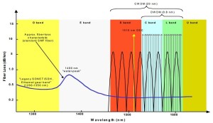
fiber loss

Because of CWDM system has wide wavelength spacing and low demand to technical parameters of laser. Since wavelength spacing up to 20 nm, the system maximum wavelength shift can reach -6.5℃~+6.5 ℃, the emission wavelength of laser precision can be up to +/- 3nm, and the working temperature range (-5℃~70℃), wavelength drift caused by temperature change is still in the allowable range, laser without temperature control mechanism, so the structure of the laser greatly simplified, yield improvement.

In addition, the larger wavelength spacing means recovery device/solution of multiplexer structure is greatly simplified. CWDM system, for example, the CWDM Filter layer coating layer can be reduced to 50, and DWDM system of 100 GHZ filter film coating layer number is about 150, resulting in increased yield, cost reduction, and the filter supplier has greatly increased competition. CWDM filter cost less than the cost of DWDM filter about more than 50%, and with the increase of automation production technology, it will be further reduction.

Still CWDM positioning the short distance transmission in metropolitan area network (within 80 km), and channel rate is generally not more than 2.5 Gbps, so there is no need for light amplification, dispersion, nonlinear and other considerations in the transmission lines, then you can make the system is simplified.

By means of some of these, by expanding wavelength spacing and simplifying equipment, the cost of optical channel made the CWDM system unit can be reduced to 1/2 or even 1/5 of the DWDM system, it has strong advantages in the metropolitan area network access layer.

Fiberstore is a quite professional store of providing optical fiber products, if you want to know more related products information, welcome to contact us.