PAM4 for 100G and 400G Applications

Hyper-scale data centers have been seeking for transceiver solutions with higher port densities and lower cost per bit, which has driven the development of PAM4 (Four-Level Pulse Amplitude Modulation) technology. Compared to the expensive multi-state coherent modulation scheme, simple PAM4 can deliver the right combination of speed, low cost, and low power consumption in data centers. This article is intended to introduce PAM4 for 100G and 400G applications.

What Is PAM4?

PAM4 is a technology that uses four different signal levels for signal transmission and each symbol period represents 2 bits of logic information (0, 1, 2, 3). By transmitting two bits in one symbol slot, PAM4 halves the signal bandwidth. With half of the bandwidth, PAM4 can achieve 50Gb/s data rate transmission in the 25Gb/s electrical tolerance environment. Also, PAM4 can minimize signal degradation and double the data rate. PAM4 allows us to put more data onto the existing fiber. In other words, if you want to increase bandwidth, you don’t have to reconfigure the data center with more fibers, just using advanced modulation PAM4 technology to increase the data rate. These components for single-lambda 100G can be extended to 400Gbps transceivers with four-channel drivers and CWDM4 wavelengths. However, these advanced modulation techniques impose additional requirements on the optical components used, especially consume higher amounts of electrical power.

alt What Is PAM4?

PAM4 or CWDM4 for 100G and 400G Applications

Although speed is important in the data center, economics and special constraints make cost and complexity more important than speed. Most of the data centers have already worked toward 100G, 200G, and even 400G with the technology of PAM4 and CWDM4, so which is the best for 100G and 400G application?

PAM4 for 100G and 400G Applications

PAM4 is considered to be a cost-effective and efficient alternative solution for 100G and 400G construction. For 100G transceiver modules, single-wavelength PAM4 technology reduces the number of lasers to one and eliminates the need for optical multiplexing. For 400G, the largest cost is expected to be optical components and related RF packages. PAM4 technology uses four different signal levels for signal transmission. It can transmit two bits of logic information per clock cycle and double the transmission bandwidth, thus effectively reducing transmission costs. This effectively solves the problem of high cost while meeting bandwidth improvements.

CWDM4 for 100G and 400G Applications

CWDM4 (Coarse Wavelength Division Multiplexing) technology is another cost-effective solution for large-scale deployment and migration in data centers. For 100G and 400G networks, the network architecture uses four lanes of 25 Gb/s, using CWDM technology to transport 100G and 400G optical traffic on duplex single mode fiber (SMF). WDM reduces the number of fibers required to achieve this type of transmission, ultimately reducing the cost of the entire board.

Conclusion

As a popular signal transmission technology for high-speed signal interconnection in next-generation data centers, PAM4 signals are widely used for electrical and optical signal transmission on 100G, 200G, and 400G interfaces. There are also a large number of PAM4 QSFP28 and PAM4 SFP28 modules available on the market to help you build your network.

Related Articles:
Global Optical Transceiver Market: Striding to 200G and 400G
Decoding 100G QSFP28 Transceiver

The Arrival of 25G CWDM SFP28

With the ever-increasing demands for faster speed and higher density, SFP transceiver modules have undergone several generations of upgrade for signal speed capability and port density updates, from the original SFP to SFP+ and then to the new SFP28 type. 10GbE has encountered bottlenecks due to the surge in demand for high bandwidth. 25G Ethernet becomes the new standard that provides significant density, cost, and power advantages for server switching links. Today we will come to know the CWDM SFP28 with 25G Gigabit Ethernet.

What Is 25G CWDM SFP28?

CWDM SFP28 transceiver operates on four wavelengths (1270, 1290, 1310, and 1330 nm), which combine to be suitable for 100G in data center networks through course wavelength division multiplexing (CWDM). It is an enhanced version of SFP+ designed for 25G signal transmission. The maximum reach is 10 kilometers. The physical structure of the SFP28 is the same as the popular SFP module and SFP+ module, but the electrical interface is upgraded to 25Gbps per channel. The optical connection of CWDM SFP28 is duplex LC fiber patch cables, and the CWDM SFP28 shall be backward compatible with the traditional 10G SFP + pluggable. 25G CWDM SFP28 is a dual directional device with a transmitter, a receiver and a control management interface (2-wire interface) in the same physical package. The 2-wire interface is used for serial ID, digital diagnostics and module control functions. This module provides very high functionality and integration and is accessible via a two-wire serial interface.

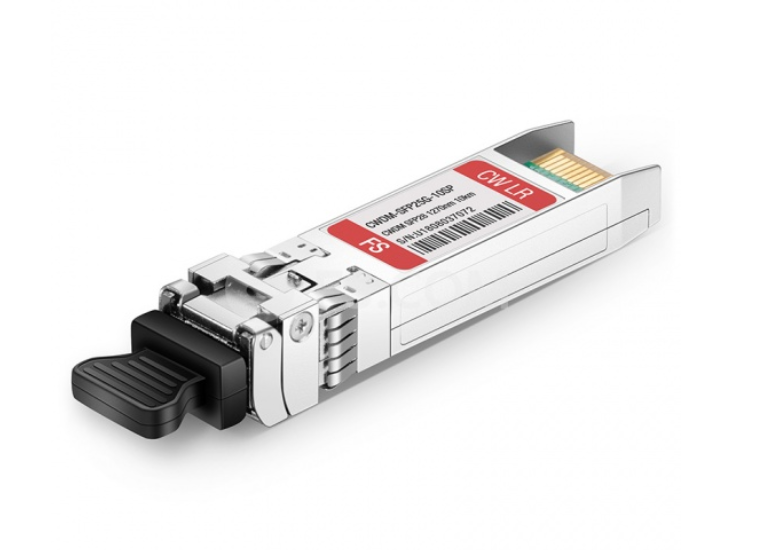
altThe Arrival of 25G CWDM SFP28

What Is the Difference Between CWDM SFP28 and CWDM SFP+?

We know that SFP+ is made to operate at 10Gb/s. SFP28 uses the same common form factor as SFP+, but the electrical interface is upgraded to 25Gbps per channel. CWDM SFP+ transceiver often operates at a nominal wavelength of CWDM wavelength. To be specific, CWDM SFP+ transceiver can support 18 wavelengths from 1270nm to 1610nm, and its transmission distance is from 20km to 80km. While CWDM SFP28 has four main wavelengths of 1270nm, 1290nm, 1310nm, and 1330nm. And its maximum transmission distance is 10km. Compared to SFP+ solutions, SFP28 has higher bandwidth, superior impedance control, and less crosstalk. A report once said the price of per unit of 10G bandwidth for 25G server Ethernet adapters is much lower. 25G SFP28 provides 2.5 times the bandwidth, but the price is not 2.5 times. All in all, the main advantages of SFP28 over SFP+ can be summarized into two points: lower cost and higher bandwidth.

Advantages of Using 25G CWDM SFP28

Compared to 4G, the spectrum bandwidth used by 5G has increased rapidly. 4G uses a maximum spectrum bandwidth of 20MHz, while 5G low-frequency band uses 100MHz bandwidth, and 5G high-frequency band (millimeter wave) uses 800MHz bandwidth with an upper limit of 1GHz. At present, there is still some difficulty in data processing and transmission of 5G high-frequency band (millimeter wave) and large bandwidth. Considering the smooth evolution of 5G equipment and the development of the industry chain, 25G CWDM SFP28 solution can well solve the current 5G millimeter wave pre-transmission problem. In this case, one 100G QSFP28 optical module is used on the antenna side and four 25G CWDM SFP28 optical modules are used on the baseband side. The construction of a 5G millimeter wave pre-transmission bearer network can be completed with only one MUX/DeMUX bridge connection. There is no need for devices to add an additional shunt function to perform rate matching on both ends. In all, 25G CWDM SFP28 can cost-effectively upgrade network bandwidth to support next-generation 50G (2x25G ), 100G (4X25G) and storage solutions for cloud and web-scale data center environments.

Conclusion

SFP28 assembly solution supports a new generation of high-density 25G Ethernet switches that facilitate server connectivity in data centers and provide a cost-effective upgrade path for enterprises deploying 10G Ethernet links in the future. If you are considering to build a 25 Gigabit Ethernet network, you can visit FS.COM, which offers a variety of CWDM SFP28 with famous compatible brands.

Related Articles:
Taking an In-depth Look at 25G SFP28
Decoding 100G QSFP28 Transceiver
How to Add CWDM MUX/DEMUX System to Your Network?

Coarse wavelength division multiplexing (CWDM) technology is developed to expand the capacity of a fiber optic network without requiring additional fiber. In a CWDM system, CWDM Mux/Demux (multiplexer/demultiplexer) is the most important component. Usually, a CWDM Mux/Demux is used to increase the current fiber cable capacity by transmitting multiple wavelengths, typically up to 18 separate signals over one fiber. This article may mainly describe what is Mux in networking and how to install your CWDM Mux/Demux system. Unless you are an experienced user, we recommend that you follow the detailed installation steps described in the rest of this article.

Introduction to CWDM MUX/DEMUX Module

CWDM Mux/Demux module is a passive device, very reliable and simple to use. These devices are available with a variety of wavelength combinations, usually from 1270nm to 1610nm (20nm spacing). Based on different applications, a CWDM Mux/Demux module can be designed into different channels. A typical 4 channel Mux/Demux module will be used to multiplex four different wavelengths onto one fiber (shown in the picture below). This allows you to simultaneously transmit four different data over the same fiber. If you are using a CWDM multiplexer at the beginning of your network, you will use a CWDM demultiplexer at the opposite end to separate or demultiplex the wavelengths to allow them to be directed to the correct receivers. Usually, a CWDM Mux/Demux is a module that can be used as a multiplexer or demultiplexer at either end of the fiber cable span. However, it must still be used in pairs.

What IS MUX in Networking?

What is MUX in networking? A basic CWDM Mux/Demux system comprises a Local unit, the CWDM Mux/Demux module and a Remote unit. Usually, a Local or Remote unit refers to two different switches. In general, to install a CWDM Mux/Demux module, a chassis should be installed first to hold the module. Besides, to connect a CWDM Mux/Demux module to a switch, we should install CWDM SFP transceivers in the switch first. Then using the single mode patch cables to connect the transceivers to the CWDM Mux/Demux module. Therefore, when we want to build a CWDM Mux/Demux system, the components we need usually include rack-mount chassis, CWDM Mux/Demux module, CWDM SFP transceiver and single mode patch cables (shown in the table below).

Part Name Product Photo Description
Rack-mount Chassis 2-Slot Chassis Customized Empty  Rack Chassis to hold 2/3/4/12 Pieces custom small size LGX Cassette
CWDM Mux/Demux CWDM Mux & Demux 2/4/5/8/9/16/18 Channels CWDM MUX DEMUX 1270nm to 1610nm with Monitor Port
CWDM SFP Transceiver CWDM SFP 1.25Gbps CWDM SFP 1270nm to 1610nm 20/40/80/100/120km Transceiver
Singlemode Fiber Cables singlemode patch cable LC to LC 9/125 Simplex/Duplex Single-mode Fiber Patch Cable

How to Add CWDM MUX/DEMUX System to Your Network?

After knowing what is MUX in networking? Next, we’ll learn how to install a CWDM Mux/Demux system, there are four basic steps:

  • Install the Rack-Mount Chassis

The CWDM rack-mount chassis can be mounted in a standard 19-inch cabinet or rack. When to attach the chassis to a standard 19-inch rack, ensure that you install the rack-mount chassis in the same rack or an adjacent rack to your system so that you can connect all the cables between your CWDM Mux/Demux modules and the CWDM SFP transceivers in your system.

  • Install the CWDM Mux/Demux Modules

To insert a module, you should align the module with the chassis shelf (shown in the figure below) first and then gently push the module into the shelf cavity. Finally, tighten the captive screws.

  • Connect the CWDM Mux/Demux to Switch

After inserting the CWDM SFP transceiver into the switch, then we should use the single mode patch cable to connect the transceiver to the CWDM Mux/Demux.

Please mind that CWDM Mux/Demux pairs must carry transceivers with the same wavelength. Because each transceiver will work only at the appropriate port and the data will always flow between devices with the same wavelengths. CWDM SFP transceivers with different wavelength may have a different color code. Use the CWDM SFP transceiver color codes shown in the picture below to help you connect the CWDM Mux/Demux to your system.

  • Connect the CWDM MUX/DEMUX Pairs

Once you use a CWDM multiplexer on one end of your networks, you must use a demultiplexer on the other end of the networks. Therefore, the last step to complete CWDM Mux/Demux system is to connect the Mux/Demux pairs (or multiplexer and demultiplexer). For duplex Mux/Demux, a pair of single mode patch cables must be used. For simplex Mux/Demux, only one single mode patch cable is enough. After all done, your CWDM Mux/Demux system is then installed successfully.

Conclusion

What is MUX in networking? In summary, Mux/Demux system is a cost-effective solution which is easy to install. CWDM Mux/Demux, CWDM multiplexer only, and CWDM demultiplexer only are a flexible, low-cost solution that enables the expansion of existing fiber capacity and let operators make full of use of available fiber bandwidth in local loop and enterprise architectures. Fiberstore CWDM Mux/Demux is a universal device capable of multiplex multiple CWDM (1270~1610nm) up to 18 channels (2, 4, 5, 8, 9, 16, 18 channels are available) or optical signals into a fiber pair or single fiber. Together with our CWDM transceivers or the wavelength converters, the bandwidth of the fiber can be utilized in a cost-effective way.

Things to Know Before Selecting CWDM SFP Transceivers

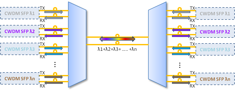
As an extension of wavelength division multiplexing (WDM), coarse wavelength division multiplexing (CWDM) is a technology that multiplexes a number of optical carrier signals onto a single optical fiber through the use of different wavelengths (i.e., colors) of laser light. A CWDM SFP (Small Form-factor Pluggable) transceiver is a hot-swappable input/output device that plugs into an SFP port or slot of a switch or router, linking the port with the fiber-optic network. It is a  kind of optical-electric/electric-optical converter. With the transmitter on one end, the CWDM SFP transceiver takes in and converts the electrical signal into light, after the optical fiber transmission in the fiber cable plant, the receiver end again converts the light signal into electrical signal. The following figure shows the CWDM SFP transceiver in the CWDM system. In the figure, TX represents “transmit”, RX represents “receive”. Being a kind of compact optical transceiver, CWDM SFP transceiver is widely used in optical communications for both telecommunication and data communication. It is designed for operations in Metro Access Rings and Point-to-Point networks using Synchronous Optical Network (SONET), SDH (Synchronous Digital Hierarchy), Gigabit Ethernet and Fibre Channel networking equipment.

CWDM SFP

Three Components of CWDM SFP Transceivers

The CWDM SFP transceiver consists of an un-cooled CWDM Distributed Feed Back (DFB) laser transmitter, a PIN photodiode integrated with a Trans-impedance Preamplifier (TIA) and a Microprogrammed Control Unit (MCU). The DFB laser used in the CWDM SFP transceiver transmitter is a 18 CWDM DFB wavelengths laser. It is well suited for high capacity reverse traffic. Obeying the standard diode equation for low frequency signals, The PIN photodiode has a 80km transmission distance. And the MCU is a high-speed, executive, input-output (I/O) processor and interrupt handler for the NRL Signal Processing Element (SPE).

Advantages of CWDM SFP transceivers

Using existing fiber connections efficiently through the adoption of active wavelength multiplexing, CWDM SFP transceivers have improved the designs of telecommunications devices and other technologies. Here are some advantages of CWDM SFP transceivers:

  • Scalability and Flexibility—CWDM SFP transceivers can support multiple channels. It means that more channels can be activated as demand increases. CWDM SFP transceivers have a wide variety of network configurations that range from the meshed-ring configurations to the multi-channel point-to-point. In point-to-point configurations, the two endpoints will connect directly through a fiber link, allowing users to add or delete as many as eight channels at a time.
  • Low Risks in Investment—Most CDWM SFP transceivers have a low failure rate, which is less likely to be the reason why the user’s solution fails. It helps enterprises increase the bandwidth of the Gigabit Ethernet optical infrastructure without adding any additional fiber strands and can also be used in conjunction with other SFP devices on the same platform. Thus the user will be able to re-invest the capital saved by avoiding prematurely failed devices.
Selecting a Right CWDM SFP Transceiver

There are many kinds of CWDM SFP transceivers in the market. Their wavelengths are available from 1270 nm to 1610 nm, with each step 20 nm. Different CDWM SFP transceivers have different color codes, distances, date rates and laser operating wavelengths. For example, the CWDM-SFP-1470, which is colored gray, is one of Cisco CWDM SFP. It is a CWDM SFP transceiver that rates for distances up to 80 km and a maximum bandwidth of 1Gbps, operating at 1470nm wavelength. Customers may choose a CWDM SFP transceiver in accordance with their actual needs.

Cisco CWDM-SFP-1470

Applied to the access layer of Metropolitan Area Network (MAN), CWDM is a low-cost WDM transmission technology. Fiberstore provides the aforesaid CWDM-SFP-1470 and other types of CWDM SFP transceivers, which are convenient and cost-effective solution for the adoption of Gigabit Ethernet and Fibre Channel in campus, data center, and metropolitan-area access networks.

The Introduction of CWDM Systems Access and Backhaul

Coarse WDM systems have been in wide use for metropolitan area backhaul and business access since the very beginning of the twenty-first century. They are based on up to 18 CWDM channels spaced 20 nm in the wavelength region 1270-1610 nm, as defined in ITU-T Recommendation G.694.2. In the beginning, CWDM price had the advantage of being cheaper than DWDM price since CWDM components do not requirement temperature control or stabilization. This advantage is expected to decrease since CWDM transceivers are not wideband tunable. DWDM transmitters, on the other hand, are full-band tunable. This allows cost reduction in manufacturing since only a single type of transmitter needs to be produced. It also allows operational cost reductions, since, for example, sparing and also network planning are greatly simplified.

In many cases, CWDM was used for (DSLAN, GPON, wireless 2G/3G) backhaul, running one or multiple GbE services per wavelength. Up to 4GbE signals can be multiplexed at wire speed (after 10B/8B decoding) onto muxponders running at 4.3Gb/s. In CWDM backhaul, this bit rate is relevant because it has similar cost than 2.5 Gb/s. This low cost ws originally driven by transmission of 4Gb/s Fibers Channels(FC) signals. In general DWDM transmission, 4Gb/s per channel is almost irrelevant due to its lack of spectral efficiency. Capacity increase up to 16 x 10 Gb/s has also been demonstrated with CWDM.

Backhaul topologies are often rings, a four-node CWDM ring with a hub node and three optical add-drop multiplexer (OADM) sites. For monitoring purposes, the OADMs can be connected to a network operations center (NOC) via an embedded communication channel (ECC). The ECC can transport narrowband management information.

CWDM systems often use CWDM-colored small form-factor pluggables (SFPs)  as remote interfaces. These can be accommodated directly in the client systems, or on transponders/muxponders. Per-channel bit rates of 1.25-4.3 Gb/s are covered (where 4.3 Gb/s share the transceiver technology with 4G Fiber Channel, which is one of the drivers behind the advantageous economics). Ten gigabit per second CWDM-fixed-wavelength extended form-factor pluggables (XFPs) also exist, but are typically restricted to the wavelengths 1470-1610 nm. In effect, these pluggables are versions of the respective DWDM transceivers, and, hence, unlike their lower bit rate counterparts, do not have significant cost advantages. Consequently, their relevant specifications are similar to the DWDM XFP specifications. So far, dedicated CWDM 40 or 100 Gb/s transceivers have not been built, and it is unlikely this will ever happen. For 4 and 10 Gb/s, reduced chromatic dispersion (CD) allowance and also power budget must be considered. This may limit maximum reach, without added means like CD compensation (not commonly used in CWDM systems), or forward error correction (FEC) to < 60 km.

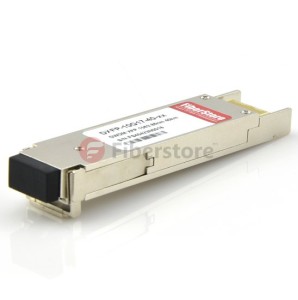
DWDM xfp

Typically, in CWDM systems, effects of polarization-mode dispersion (PWD), polarization-dependent loss (PDL), and nonlinearity are covered within the transceiver specifications, due to distance limitations. If link lengths approach the respective specified CD limits, power budget penalties in the 1dB range may have to be applied.

FiberStore designs, manufactures, and sells a broad portfolio of optical communication products, including passive optical network, or PON, subsystems, optical transceivers used in the enterprise, access, and metropolitan segments of the market, as well as other optical components, modules, and subsystems. If you have trouble in these aspects, you can visit our fiberstore. http://www.fiberstore.com/

Article Source: http://www.fiber-optical-networking.com/