Different Ports on WDM Mux/Demux

In the WDM (wavelength-division multiplexing) system, CWDM (coarse wavelength-division multiplexing) and DWDM (dense wavelength-division multiplexing) Mux/Demux (multiplexer/demultiplexer) modules are often deployed to join multiple wavelengths onto a single fiber. Multiplexer is for combining signals together, while demultiplexer is for splitting signals apart. On a WDM Mux/Demux, there are many kinds of ports for different applications. This article will discuss the functions of these ports on WDM Mux/Demux.
WDM Mux/Demux

Necessary Ports on WDM Mux/Demux

Channel port and line port are the necessary ports to support the basic function of WDM Mux/Demux to join or split signals in the data network.

Channel Port

A WDM Mux/Demux usually has several channel ports on different wavelengths. Each channel port works for a specific wavelength. Since there are 18 wavelengths of CWDM ranging from 1270 nm to 1610 nm with a 20nm interval, the number of channel ports on CWDM Mux/Demux also ranges from 2 to 18. DWDM has a more dense wavelength spacing of 0.8 nm (100 GHz) or 0.4 nm (50 GHz) ranging from S-Band to L-Band around 1490 nm to 1610 nm. The number of DWDM Mux/Demux channel ports is about 4 to 96 for high-density networks.

Line Port

Each WDM Mux/Demux will have a line port connecting to the network backbone. Combined channels are transmitted or received at the line port. In addition, line port can be divided into dual-fiber and single-fiber types. Dual-fiber line port is used for bidirectional transmission, therefore the transmit and receive port in each duplex channel must support the same wavelength. However, single-fiber line port only supports one direction data flow, thus the transmit and receive port of duplex channel will support different wavelengths. The wavelengths’ order of single-fiber WDM MUX/DEMUX should be reversed at both sides of the network.

Special Ports on WDM Mux/Demux

Apart from the necessary ports, some special ports can also be found on WDM Mux/Demux for particular needs.

1310nm Port and 1550nm Port

1310nm and 1550nm ports are certain wavelength ports. Since a lot of optical transceivers use these two wavelengths for long-haul network, adding these two ports when the device does not include these wavelengths is very important. CWDM Mux/Demux can add either type of wavelength ports, but the wavelengths which are 0 to 40 nm higher or lower than 1310 nm or 1550 nm cannot be added to the device. However, DWDM Mux/Demux can only add 1310nm port.

Expansion Port

Expansion port can be added on both CWDM and DWDM Mux/Demux modules. This is a special port to increase the number of available channels carried in the network. That is to say, when a WDM Mux/Demux can not meet all the wavelength needs, it is necessary to use the expansion port to add different wavelengths by connecting to another WDM Mux/Demux’s line port.

Monitor Port

Monitor port is used for signal monitoring or testing. Network administrators will connect this port to the measurement or monitoring equipment to inspect whether the signal is running normally without interrupting the existing network.

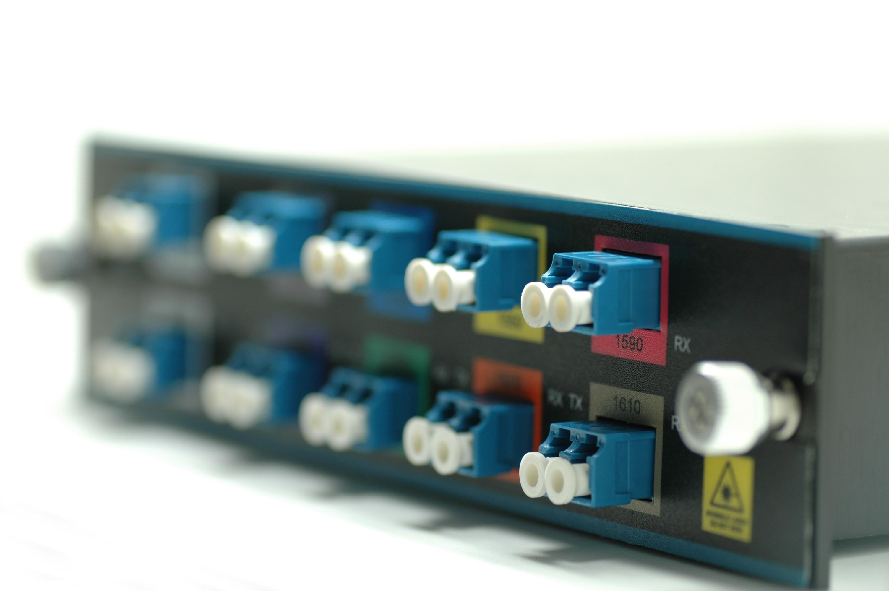
ports on WDM mux demux

Conclusion

From this post, we can know that a WDM Mux/Demux has multiple types of ports. Channel and line ports are integral ports for normal operation of the WDM Mux/Demux. 1310nm port, 1510nm port, expansion port and monitor port are used for special requests of the WDM application. Hence, you should have a thorough consideration of your project before choosing the WDM Mux/Demux module.

Related Articles:
18 Channel CWDM Mux/Demux for 10G Network
What Is DWDM?

Getting to Know Optical Circulator

The utilization of optical circulator starts from the 1990s, and now it has become one of the important elements in advanced optical communication systems. Similar to the function of an electronic circulator, an optical circulator is used to separate optical signals that travel in opposite directions in an optical fiber. Optical circulator has been widely applied to different fields, such as telecom, medical and imaging industries. Are you ready to know more about this optical device? This article will take you to explore the secrets of optical circulator.

optical-circulator

What Is Optical Circulator?

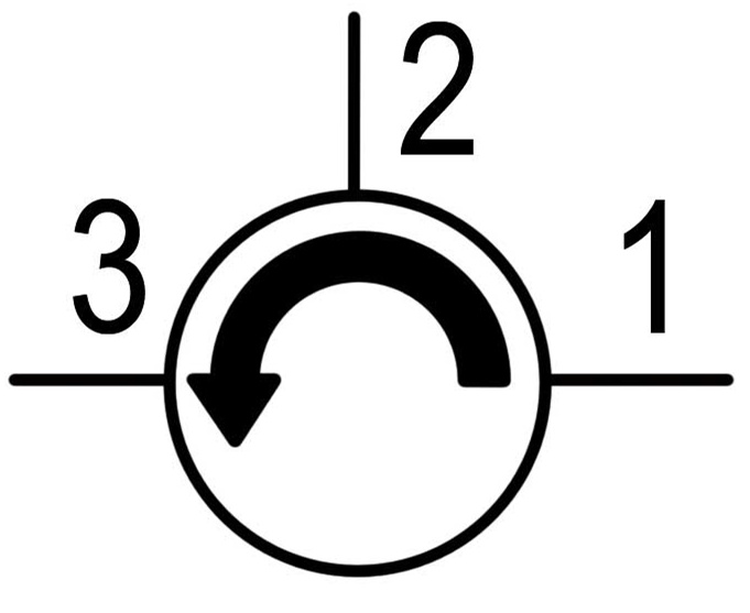
An optical circulator is built to pass light from one optical fiber to another. It is a non-reciprocal device routing the light based upon the direction of light propagation. Both optical circulator and optical isolator can be used to move light forward. However, there is typically more loss of light energy in the optical isolator than in the optical circulator. Optical circulator usually consists three ports: two ports are used as input ports and one port as output port. A signal is transmitted from port 1 to port 2, and another signal is transmitted from port 2 to port 3. Finally a third signal can be transmitted from port 3 to port 1. Many applications only require two, so they can be built to block any light that hits the third port.

optical-circulator-structure

Technologies of Optical Circulator Components

An optical circulator includes the components of Faraday rotator, birefringent crystal, waveplate, and beam displacer. The Faraday rotator uses the Faraday effect, which is a phenomenon that the polarization plane of an electromagnetic (light) wave is rotated in a material under a magnetic field applied parallel to the propagation direction of the lightwave. The light propagation in the birefringent crystal depends on the polarization state of the light beam and the relative orientation of the crystal. The polarization of the beam can be changed or the beam can be split into two beams with orthogonal polarization states. Waveplate and beam displacer are two different forms of birefringent crystal. A waveplate can be made by cutting a birefringent crystal to a particular orientation so that the optic axis of the crystal is in the incident plane and is parallel to the crystal boundary. Beam displacer is used to split an incoming beam into two beams with orthogonal polarization states.

Categories of Optical Circulator

According to polarization, optical circulator can be divided into polarization-dependent optical circulator and polarization-independent optical circulator. The former is used for the light with a particular polarization state, and the latter is not restricted to the polarization state of a light. Most of the optical circulators employed in fiber optic communications are designed to be polarization-independent.

According to functionality, optical circulator can be classified into full circulator and quasi-circulator. As mentioned before, full circulator makes full use of all ports in a complete circle. Light passes through from port 1 to port 2, port 2 to port 3, and port 3 back to port 1. About quasi-circulator, light passes through all ports sequentially but light from the last port is lost and cannot be transmitted back to the first port. For most applications, a quasi-circulator is enough.

Several Applications of Optical Circulator
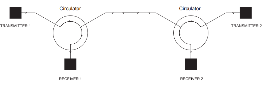
  • Duplex Transmitter/Receiver System: Optical circulators can be used to enable 2-way transmission along a single fiber. Transmitter 1 sends signal through Port 1 of Circulator 1 and through the fiber to Port 2 of Circulator 2 so that it is directed to Receiver 2. The signal from Transmitter 2 follows the opposite path to Receiver 1.

duplex-transmitte-receiver-system

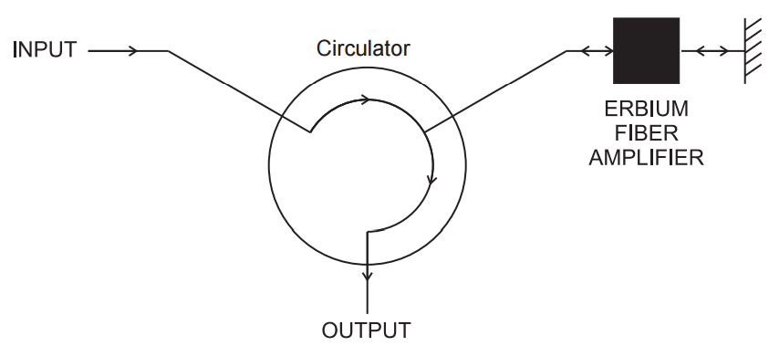
  • Double Pass Erbium Doped Amplifier: This technique allows high gain amplification of a signal through an erbium doped fiber amplifier. The signal passes through optical circulator and optical amplifier, returns from the fiber optic reflector and passes through the amplifier again. This amplified signal is directed through the return port.

double-pass-erbium-doped-amplifier

  • Wave Division Multiplexing System: Optical circulators in conjunction with Bragg gratings allow specific wavelengths to be reflected and sent down different paths.

wave-division-multiplexing-system

Conclusion

From this article, you may have a basic impression about optical circulator. It is an efficient and economical solution to use optical circulator for directing light signal with minimum loss. If you are interested in the optical circulator products, welcome to visit fs.com for more information.

Overview of PON Network

PON has now became a popular network technology all over the globe. It first came in to being in 1995. The International Telecommunication Union (ITU) standardized two initial generations of PON – APON and BPON. And the advancement of PON network has never stopped. Until now, the recent PON standard of NG-PON2 has been put forward in 2015. With the maturity of PON, people are more easily accessible to networks today. But what does PON exactly mean? What’s the composition of PON network? The following part will give you the answer.

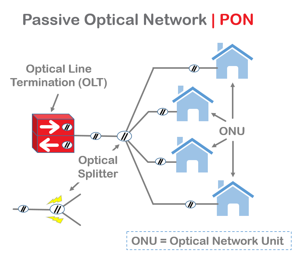
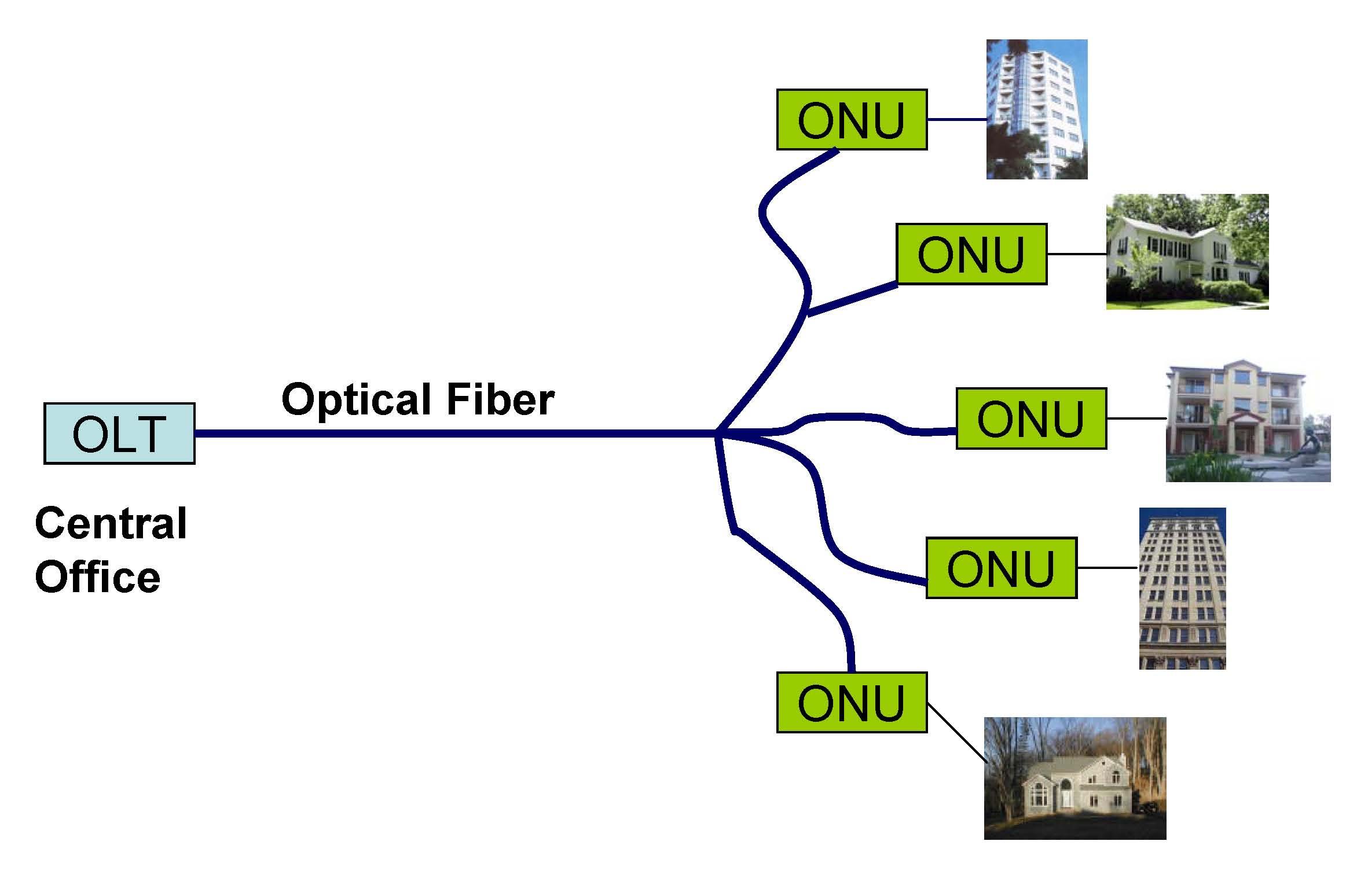
PON, also known as passive optical network, is a technology in telecommunication that implements a point-to-multipoint (P2MP) architecture. Unpowered fiber optic splitters are used to enable a single optical fiber to serve multiple end-points such as customers instead of providing individual fibers between the central office (hub) and customer. According to different terminations of PON, the network system can be divided into fiber-to-the-home (FTTH), fiber-to-the-curb (FTTC), fiber-to-the-curb (FTTB), etc. To be specific, a PON is made up of an optical line terminal (OLT) at the service provider’s hub and a number of optical network units (ONUs) or optical network terminals (ONTs) near end users. And “passive” is just used to describe that no power requirement or active electronic component is included for transmitting signals in the system.

PON network

Types of PON Network

Here are some types of PON that have been used throughout the years:

1) APON

Its full name is asynchronous transfer mode (ATM) passive optical network. As the original PON system, APON uses ATM technology to transfer data in packets or cells of a fixed size. In APON, downstream transmission is a continuous ATM stream at a bit rate of 155 Mbps or 622 Mbps. Upstream transmission is in the form of bursts of ATM cells at 155 Mbps.

2) BPON

BPON, also known as broadband PON, is the improved version of APON. It adopts wavelength division multiplexing (WDM) for downstream transmission with the transmission rate up to 622 Mbps. It also provides multiple broadband services such as ATM, Ethernet access and video distribution. Today, BPON is more popular than APON.

3) EPON

EPON or Ethernet PON uses the Ethernet packets instead of ATM cells. Upstream and downstream rates of EPON are able to achieve up to 10 Gbps. It is now widely applied to FTTP or FTTH architecture to serve multiple users. With the advantages of scalability, simplicity, multicast convenience and capability of providing full service access, many Asian areas adopt EPON for their networks.

4) GPON

Gigabit PON is the development of BPON. It supports various transmission rates with the same protocol. The maximum data rate of downstream is 2.5 Gbps and upstream is 1.25 Gbps. It is also widely used for FTTH networks. But compared with EPON, its burst sizes and physical layer overhead are smaller.

Advantages of PON

  • Low cost, simple maintenance, flexible extensibility and easy to upgrade. And no need for power during transmission saves a lot for long-term management.
  • Using pure media network avoids the interference of lightning and electromagnetism. Thus PON network is suitable for areas under harsh conditions.
  • Low occupancy of central office resources, low initial investment and high rate of return.
  • As the P2MP network, PON is able to provide a large range of service to plenty of users.

Conclusion

PON network is for sure an effective solution for multiple network users. EPON and GPON are the most commonly deployed PON systems at present. Since people have been seeking for higher bandwidth provisioning, the capability of transmission will be greatly improved in the near future.

Related Articles:
AON vs PON Networks: Which One to Choose for FTTH Systems
ABC of GPON SFP: Understanding GPON OLT / ONU / ONT SFP Module

Technologies Used in Multiplexing

Sending email is a commonplace occurrence in our daily life. When you send an email to a friend in another city, it will firstly join up with other messages being transmitted in your city, and then get dropped off at the correct destination in the correct city. How do all of these messages get to join together and be transmitted without getting mixed up? This process is achieved through the use of multiplmexing technology, which is a method that combines multiple analog message signals or digital data streams into one signal over a shared medium. Actually, multiplexing is widely used in many telecommunications applications. This article will introduce multiplexing technology from the aspect of common technologies used in multiplexing.

Optical multiplexing filter is an essential component in multiplexing technology, which is a physical device that combines each wavelength with other wavelengths (as shown in the following figure). Many technologies are applied in multiplexing, including thin-film filter (TFF), fiber bragg grating (FBG), arrayed waveguide grating (AWG) and interleaver, periodic filter, and frequency slicer.

filter

TFF

Optical TFF typically consists of multiple alternating layers of high- and low-refractive-index material deposited on a glass or polymer substrate. This substrate is made to let only photons of a specific wavelength pass through, while all others are reflected.

FBG

A bragg grating is made of a small section of fiber that has been modified by exposure to ultraviolet radiation to create periodic variations in the refractive index of the fiber. And the process of creating periodic variations will generate wavelength-specific dielectric mirrors. Thus, the FBG can reflect particular wavelengths of light and transmit all others.

AWG

AWG devices can multiplex a large number of wavelengths into a single optical fiber. These devices are designed on the fundamental principle of optics that light waves of different wavelengths interfere linearly with each other. That’ to say, if each channel in an optical communication network makes use of light of a slightly different wavelength, then the light from a large number of these channels can be carried by a single optical fiber.

Interleaver, Periodic filter, and Frequency Slicer

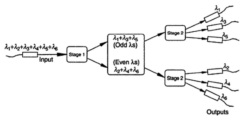
Interleaver, periodic filter and frequency slicer are often used together to perform the function of multiplexing. The following figure shows how interleaver, periodic filter and frequency slicer work together to make a multiplexer device. Periodic filter is in stage 1, which is an AWG. Stage 2 represents the frequency slicer which is another AWG. The interleaver is at the output part, which is provided by six bragg gratings. Six wavelengths (λ) are received at stage 1 which breaks the wavelengths down into odd and even wavelengths. Then the odd and even wavelengths go to stage 2 respectively. Finally, they are delivered by the interleaver in the form of six discrete, interference-free optical channels.

interleaver, periodic filter and frequency slicer

All in all, the usual goal of multiplexing is to enable signals to be transmitted more efficiently over a given communication channel rather than save bandwidth. Nowadays, the most popular multiplexing technology is wavelength division multiplex (WDM), which can be divided into coarse wavelength division multiplexing (CWDM) and dense wavelength division multiplexing (DWDM). It is hoped that multiplexing technology would offer significant gains in bandwidth efficiency.

EPON VS GPON

A passive optical network (PON) is a fiber network that only uses fiber and passive components like fiber splitters and combiners. It starts from the optical line terminal (OLT) in the central office and ends at the optical network unit (ONU) at the customer’s home (as shown in the following figure). Today, we’ll talk about EPON vs GPON.

PON

EPON vs GPON: What Are the Difference?

Ethernet passive optical network (EPON) and gigabit passive optical network (GPON) are two popular versions of PONs. The most dramatic distinction between EPON and GPON is a marked difference in architectural approach. EPON employs a single Layer 2 network that uses Internet Protocol (IP) to carry data, voice, and video. While GPON provides three Layer 2 networks: ATM for voice, Ethernet for data and proprietary encapsulation for voice. Moreover, they also vary from each other in terms of bandwidth, per-subscriber cost, efficiency, management system and encryption.

  • Usable Bandwidth

EPON generally delivers 1 Gbit/s symmetrical bandwidth. And its Gigabit Ethernet service actually constitutes 1 Gbit/s of bandwidth for data and 250 Mbit/s of bandwidth for encoding. GPON, however, promises 1.25 Gbit/s or 2.5 Gbit/s downstream and upstream bandwidths scalable from 155 Mbit/s to 2.5 Gbit/s.

  • Per-subscriber Costs

EPON lowers the costs of subscribers by allowing carriers to simplify their networks and to eliminate complex and expensive asynchronous transfer mode (ATM). While the costs of EPON equipment are approximately 10 percent of the costs of GPON equipment.

  • Efficiency

According to the IEEE 802.3 protocol for Ethernet, data transmission occurs in variable-length packets of up to 1518 bytes in EPON. The use of variable-length packets makes Ethernet to carry IP traffic, which significantly reduces the overhead relative to ATM.

In GPON, data transmission occurs in fixed-length 53 byte cells as specified by the ATM protocol. This format makes it inefficient for GPON to carry traffic formatted according to IP, which calls for data to be segmented into variable-length packets of up to 65,535 bytes. This process is time-consuming and complicated.

  • Management systems

EPON requires one single management system, which means EPON results in a significantly lower total cost of ownership. In addition, it does not require multi-protocol conversions, and the result is a lower cost of silicon. In GPON, there are three management systems for the three Layer protocols. Thus it is more expensive. Furthermore, GPON does not support multi-cast services. This makes support for IP video more bandwidth-consuming.

  • Encryption

EPON uses an advanced encryption standard (AES) based mechanism, which is supported by multiple silicon vendors and deployed in the field. Furthermore, EPON encryption is both downstream and upstream. While the encryption in the GPON is part of the International Telecommunication Union (ITU) standard and GPON encryption is downstream only.

Conclusion

All in all, when EPON vs GPON, both have their advantages and disadvantages. It is hard to say which one will be prevailing. But one thing is clear: PON deployment will continue expanding. FS launches a series of integrated, high reliability and affordable EPON/GPON system solutions for its customers to meet the fast growing demand of PON deployment. In addition, network equipment like network switch, transceiver module also are available at FS.

Related Articles:
EPON SFP VS. GPON SFP: Cost-effective Solution for Access Network
PON vs. AON in FTTH Systems