The Application of TDM-PON And WDM-PON

1. Instruction
The bandwidth requirements of the telecommunication network users increased rapidly during the recent years. The emerging optical access network must provide the bandwidth demand for each user as well as support high data rate, broadband multiple services and flexible communications for various end-users. Being considered as a promising access network solution due to the high bandwidth provision and the low operation and maintenance cost, passive optical networks (PONs) represent one of the most attractive access network solutions. TDM and WDM techniques are employed in the PON for higher resource efficiency and capacity, which results in TDM-PON and WDM-PON respectively. TDM-PON provides much higher bandwidth for data application but it has limited availability to end-users. WDM PON can solve the problems encountered in TDM-PON by allocating a specified wavelength to each subscriber. This provides a separate, secure P2P, and high data-rate channel between each subscriber and the CO. This article is mainly written to give you a overview of the application of TDM-PON and WDM-PON as well as the joint application—TWDM PON.

2. Application of TDM-PON
TDM-PON types include ATM PON (APON), Broadband PON (BPON), Ethernet PON (EPON), Gigabit PON (GPON). Now EPON and GPON are extensively used in the telecommunication networks.

2.1 Application of EPON
Ethernet PON (EPON) is a PON-based network that carries data traffic encapsulated in Ethernet frames (defined in the IEEE 802.3 standard). A typical EPON system consists of three components: optical line terminal (OLT), optical network unit (ONU), and optical distribution network (ODN). Utilizing PON topological structure to achieve the access of Ethernet, EPON is equipped with the dual advantages of PON and Ethernet including low cost, high bandwidth, strong scalability, excellent compatibility with Ethernet to facilitate network management, etc. Based on where ONUs are deployed, EPON application mode can be fiber to the curb (FTTC), fiber to the building (FTTB), and fiber to the home (FTTH), as shown in Figure 1.

Application of EPON in FTTB, FTTC and FTTH

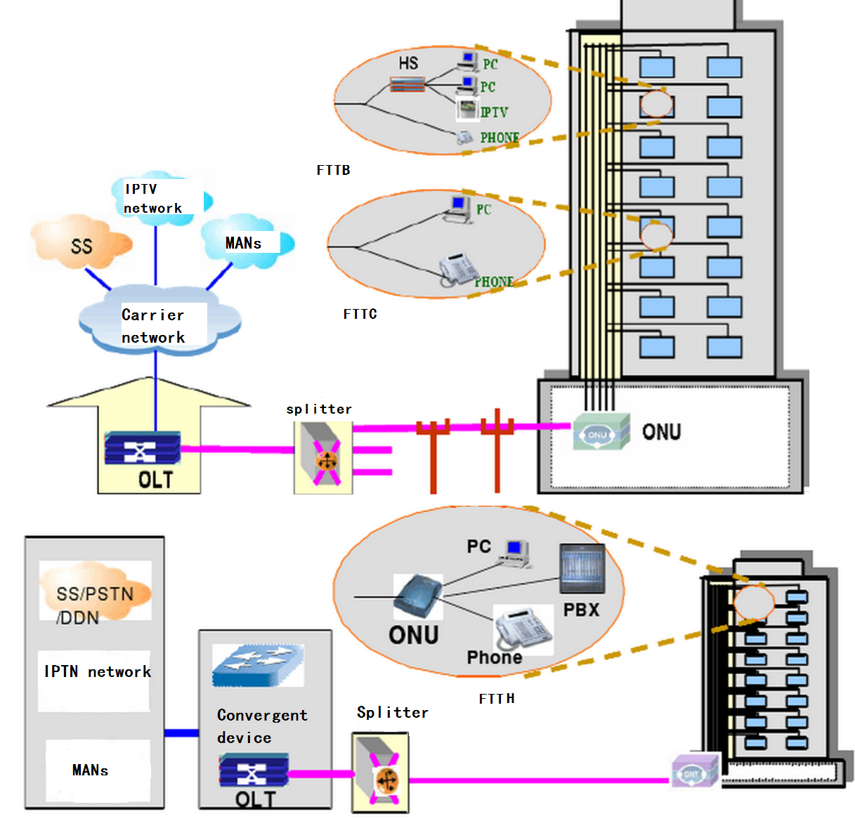
Figure 1: The application of EPON in FTTB, FTTC and FTTH

In a FTTC system, ONUs are deployed at roadside or beside the junction boxes of telegraph poles. Usually, twisted-pair copper wires are used to connect the ONUs to each user, and coaxial cables are used to transmit broadband graphic services. Currently, the FTTC technology is the most practical and economical Optical Access Network (OAN) solution for providing narrow-band services below 2 Mbps. For services integrating narrowband and broadband services, however, FTTC is not the ideal solution.

In a FTTB system, ONUs are deployed within buildings, with the optical fibers led into user homes through ADSL lines, cables, or LANs. Compared with FTTC, FTTB has a higher usage of optical fiber and therefore is more suitable for user communities that need narrowband/broadband integrated services.

In a FTTH system, ONUs are deployed in user offices or homes to implement a fully transparent optical network, with the ONUs independent of the transmission mode, bandwidth, wavelength, and transmission technology. Therefore, FTTH is ideal for the long term development of optical access networks.

2.2 Application of GPON
Gigabit PON (GPON) is the far-most advanced PON solution used by European and US providers. It is somehow based on the former ATM access networks (APON, BPON), but GPON’s data encapsulation (GEM) is more generic, and accepts different network protocols, such as ATM, Ethernet and IP. A traditional GPON system is made up of three parts: optical line terminal (OLT), optical network terminal (ONT) or ONU, and optical distribution network (ODU) composed of SM fiber and splitter. GPON possess the advantages of high bandwidth, high efficiency, large coverage, abundant user interfaces, etc. In the access network, GPON can be used to fiber to the building (FTTB), fiber to the curb (FTTC), and fiber to the home (FTTH), as shown in Figure 2.

GPON-application

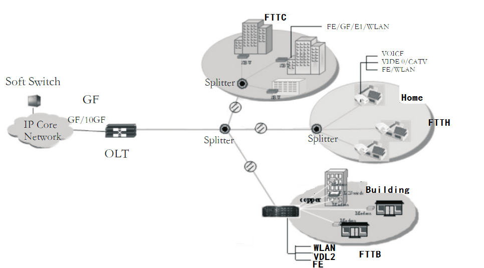
Figure 2: The application of GPON in FTTB, FTTC and FTTH

In a FTTB system, ONTs are deployed within buildings. GPON can be used to serve for the users of multi-dwelling units (MDU) as well as business users. When serving for MDU users, the services supported by GPON contains asymmetric broadband services (digital broadcast, VOD, IP TV) and symmetric broadband services (content broadcast, e-mail, remote diagnose). When serving for business users, the services supported by GPON are symmetric services (group software, content broadcast, e-mail). Facing diverse services, GPON must flexibly provide private line service at different rate.

In a FTTC system, ONTs are deployed at roadside or beside the junction boxes of telegraph poles. The services supported by GPON consists of asymmetric services ( digital broadcast, VOD, IP TV, files downloading, online games) and symmetric services (content broadcast, e-mail, files interaction, remote education). In addition, GPON supported the expansion of the dedicated line POTS and ISDN.

In a FTTH system, ONTs are deployed in user offices or homes. GPON supports the asymmetric services and symmetric services. The asymmetric services include data broadcast, VOD, IP TV, files downloading, etc. The symmetric services include content broadcast, e-mail, files interaction, remote education, remote diagnose, online games, etc. What’s more, GPON supported the expansion of the dedicated line POTS and ISDN.

3. Application of WDM-PON
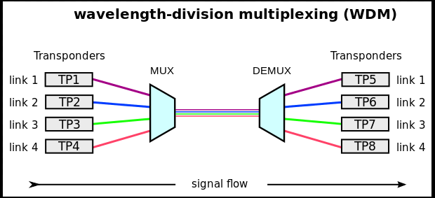
As the new-generation access network, WDM-PON makes it possible to transmit multiple wavelengths instead of one wavelength in the PON over the same fiber, thus greatly meet the bandwidth requirements of users. In addition to its efficient use of wavelengths, the WDM-PON also has advantages in its use of optical-transmission power. The network management is much simpler than a TDM-PON, and all future services can be delivered over a single network platform.

WDM-PON can be directly used to achieve FTTC, FTTB and FTTH (see Figure 3) and provide services for business subscribers, the single-family subscribers, the multi-family subscribers and other types subscribers at the same time. WDM-PON offer abundant bandwidth to better meet the bandwidth requirements of the back transmission of 3G and LTE base station, thus becoming the optimal technology for the back transmission of mobile station. WDM-PON also can be used to support reach extension and the transition of existing EPON networks to improve the scalability as well as protect the existing network investment. What’s more WDM-PON can also be adpoted to build the hybrid WDM-TDM PON which combines the dual advantages of TDM-PON and WDM-PON with TDM-PON to be better applied in the optical communication network and provide better services for subscribers. WDM-PON is very suitable for the application environment of telecommunication.

WDM-PON application

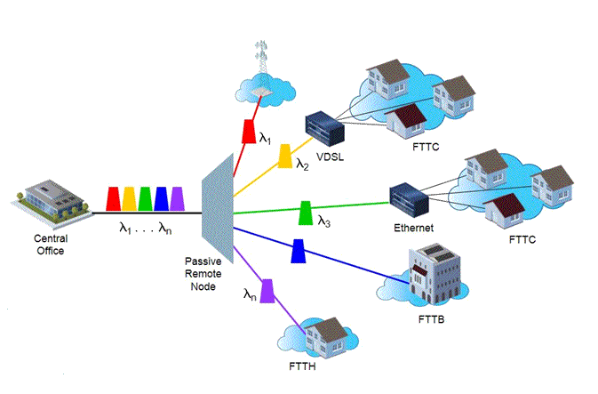
Figure 3: The application of WDM-PON in FTTC, FTTB and FTTH

4.Joint Application of TDM-PON and WDM-PON
The combination of TDM and WDM in a PON network could be the most cost effective way of introducing TDM/WDM PON into the access network, which brings TWDM-PON into being. Figure 4 shows the architecture of TWDM-PON . Four XG-PONs are stacked by using four pairs of wavelengths {(λ1, λ5), (λ2, λ6), (λ3, λ7), (λ4, λ8)}. For simple network deployment and inventory management purposes, the ONUs use colorless tunable transmitters and receivers. The transmitter is tunable to any of the upstream wavelengths, while the receiver can tune to any of the downstream ones. To achieve a power budget higher than that of XG-PON1, optical amplifiers are employed at the OLT side to boost the downstream signals as well as to pre-amplify the upstream signals. ODN remains passive since both the optical amplifier and WDM Mux/DeMux are placed at the OLT side. Taking the advantages of TDM-PON and WDM-PON and overcoming their shortcomings, TWDM-OPN can provide higher rates and bandwidth to better serve users.

TWDM-PON architecture

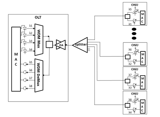
Figure 4: The network architecture of TWDM-PON

TWDM-PONcould be applied in the following ways. The first one to consider is used for pay-as-you-grow provisioning. The TWDM-PON system could be deployed by starting with a single wavelength pair. It could be upgraded by adding new wavelength pairs to increase the system capacity. In this way, the operators can address the bandwidth growth demand by investing what is needed and expanding the future demand. Another application of TWDM-PON is for local loop unbundling (LLU). A TWDM-PON with multiple OLT arrangement is shown in Figure 5 for LLU. Each operator would have their own OLT, each of which would contain some set of wavelength channels. A wavelength-selective device would be used to multiplex the OLT ports onto a single fiber. The wavelength-selective device could be as simple as a filter-based demultiplexer, or it could be an arrayed waveguide router type of device. This scheme unbundles the shared infrastructure for multiple operators. It also offers the possibility of every operator’s OLT being the same (containing all the wavelengths), and a single operator could add OLT resources as they want. What’s more, TWDM-PON can applied in the above-mentioned ways of TDM-PON and WDM-PON being applied.

TWDM-PON application for LLU

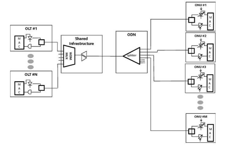
Figure 5: The application of TWDM-PON for LLU

5.Conclusion
TDM-PON and WDM-PON, as the popular optical access network , are extensively used in the communication networks. WDM-PON solves the problems of limited bandwidth to each subscriber, high transmission power and poor network security exsiting in TDM-PON, becoming the new-generation access network. However, the cost WDM-PON components are relatively high, which lessen its population. Nowadays the high-speed broadband penetration and ongoing growth of the Internet traffic among customers have been placing a huge bandwidth demand on the telecommunication network. TWDM-PON, combining the advantages of TDM-PON and WDM-PON, comes into being to become the far-most advanced PON. Being able to provide higher bandwidth, higher rates in downstream and upstream and competitive cost, TWDM-PON will plays a key role in the optical communication networks.

The Comparison Of PDH And SDH

1.Introduction
With the rapid development of internet industry, the information content transmitted, exchanged and handled by network has greatly risen. As the transmission system of internet, PDH fails to meet the application of internet now, so SDH comes into being as required. This article is written to give you a better understanding of SDH and PDH through the comparison of SDH and PDH.

2.What Is PDH and SDH?
PDH, abbreviation from plesiochronous digital hierarchy, is a popular technology applied in the networks of telecommunication in order to transport huge amounts of data over digital transport equipment like fibre optic or microwave radio systems. As shown in Figure 1, in PDH, digital multiplexer’s inputs are of same bit rate and are derived from different clocks from different oscillators. Each will differ within tolerance of few clock periods. Hence it is called plesiochronous. The term plesiochronous is derived from Greek plēsios, which means near and close time and refers to the fact that PDH networks operate in a state where different parts of the network are nearly synchronised, but not quite perfectly synchronised.

The principles of PDH

Figure 1: The working principle of PDH

SDH, short for synchronous optical networking, are standardized technology that is used for high-speed data transmission of telecommunication and digital signals. It can transfer multiple digital bit streams synchronously over optical fiber using lasers or highly coherent light from light-emitting diodes (LEDs). As shown in Figure 2, In SDH, digital multiplexer’s inputs are of same bit rate and are derived from common clock. Hence it is called synchronous.At low transmission rates data can also be transferred via an electrical interface. SDH system is designed to replace PDH system for transporting large quantities of telephonecalls and data traffic over the same fiber without synchronization problems, providing a simple and flexible network infrastructure.

The principles of SDH

Figure 2: The working principle of SDH

3.SDH Advantages over PDH
SDH is actually derived from PDH, but makes lots of improvements on the basis of PDH. Compared with PDH, SDH has a large number of advantages. The advantages enjoyed by utilization of SDH includes:
(1)The standardized optical interfaces make it very convenient for interconnection in lines.
(2)The world-standard frame structure and rate of digital signals make it easy to interconnect in the world.
(3)SDH has excellent ability of DXC.
(4)SDH is equipped with the powerful capacity of networking and network protection.
(5)Synchronous structure is flexible.
(6)SDH adopts the synchronous mapping, encapsulation and pointer to facilitate the add and the drop branches.
(7)SDH is cost-effective and reduces networking cost due to the transversal compatibility.
(8)SDH possesses forward and backward compatibility.

4.SDH Disadvantages over PDH
Though SDH has plenty of advantages compared with PDH, it still possess some disadvantages. The weaknesses of SDH is as follows.
(1)The utilization rate of SDH bandwidth is relatively low. In SDH, about one twentieth of data frames are used as the signals of management, thus resulting in the reduction of data frames utilized to transmit signals. SDH improves its maintainability but lowers the utilization rate of bandwidth.
(2)SDH is lacking in network security because of adopting the OAM as the monitoring and maintenance instrument of its following performances. As the common software, OAM is likely to be attacked by viruses or Trojans owing some bugs of designing and developing it.

5.Conclusion
With the advent of the information society, PDH fails to satisfy the internet requirements for transmitting signals. Though PDH has proved to be a breakthrough in the domain of digital transmission , it is replaced by SDH which is a very useful technology used in the telecommunication sector owing to its own weaknesses now. As the transmission system, SDH is able to transport large quantities of digital signals over the same fiber without synchronization problems, providing a simple and flexible network infrastructure. SDH system has brought a considerable amount of changes in the telecommunication networks that are based on the optical fibers as far as performance and cost are concerned.

Related Article: PDH Optical Multiplexer Wiki
Related Article: How Much Do You Know About SONET/SDH SFP Module?

The WDM System

Introduction
In fiber-optic communications, wavelength-division multiplexing (WDM) is a technology which multiplexes a number of optical carrier signals into a single optical fiber by using different wavelengths of laser light. This technique enables bidirectional communications over one strand of fiber, as well as multiplication of capacity. A WDM system (Figure 1) uses a multiplexer at the transmitter to join the signals together, and a demultiplexer at the receiver to split them apart. With the right type of fiber it is possible to have a device that does both simultaneously, and can function as an optical add-drop multiplexer. The concept was first published in 1978, and by 1980 WDM systems were being realized in the laboratory. As a system concept, the ways of WDM includes coarse wavelength-division multiplexing (CWDM) and dense wavelength-division multiplexing (DWDM).

20150417100422

Figure 1: The WDM system

The CWDM System
In simple terms, CWDM equipment performs two functions: segregating the light to ensure only the desired combination of wavelengths are used, multiplexing and demultiplexing the signal across a single fiber link.

Typically CWDM solutions provide 8 wavelengths capability, separated by 20nm, from 1470nm to 1610nm, enabling the transport of 8 client interfaces over the same fiber, as is shown in Figure 2. What’s more, CWDM has the capability to transport up to 16 channels (wavelengths) in the spectrum grid from 1270nm to 1610nm with a 20nm channel spacing. Each channel can operate at either 2.5, 4 or 10Gbit/s. CWDM can not be amplified as most of the channels are outside the operating window of the erbium doped fiber amplifier (EDFA) used in Dense Wavelength Division Multiplexing (DWDM) systems. This results in a shorter overall system reach of approximately 100 kilometers. However, due to the broader channel spacing in CWDM, cheaper un-cooled lasers are used, giving a cost advantage over DWDM systems.

20150417100626

Figure 2:The CWDM system

CWDM proves to be the initial entry point for many organizations due to its lower cost. Each CWDM wavelength typically supports up to 2.5Gbps and can be expanded to 10Gbps support. This transfer rate is sufficient to support GbE, Fast Ethernet or 1/2/4/8/10GFC, STM-1/STM-4/STM-16/OC3/OC12/OC48, as well as other protocols.

CWDM is the technology of choice for cost efficiently transporting large amounts of data traffic in telecoms or enterprise networks. Optical networking and especially the use of CWDM technology has proven to be the most cost efficient way of addressing this requirement.

In CWDM applications, a fiber pair (separate transmit and receive) is typically used to serve multiple users by assigning a specific wavelength to each subscriber. The process begins at the head end (HE) or hub, or central office (CO), where individual signals at discrete wavelengths are multiplexed, or combined, onto one fiber for downstream transmission. The multiplexing function is accomplished by means of a passive CWDM multiplexer (Mux) module employing a sequence of wavelength-specific filters. The filters are connected in series to combine the various specific wavelengths onto a single fiber for transmission to the field. In the outside plant a CWDM demultiplexer (Demux) module, essentially a mirror of the Mux, is employed to pull off each specific wavelength from the feeder fiber for distribution to individual FTTX applications.

CWDM is suitable for use in metropolitan applications, also being used in cable television networks, where different wavelengths are used for the downstream and upstream signals. In these systems, the wavelengths used are often widely separated, for example, the downstream signal might be at 1310 nm while the upstream signal is at 1550nm. CWDM can also be used in conjunction with a fiber switch and network interface device to combine multiple fiber lines from the switch over one fiber. CWDM is optimized for a cost conscience budgets in mind, with low-cost, small-powered laser transmitters enabling deployments to closely match guaranteed revenue streams.

The DWDM System
DWDM stands for Dense Wavelength Division Multiplexing. Here “dense” means the wavelength channels are very narrow and close to each other. DWDM uses the same transmission window but with denser channel spacing. Channel plans vary, but a typical system would use 40 channels at 100 GHz spacing or 80 channels with 50 GHz spacing.

DWDM works by combining and transmitting multiple signals simultaneously at different wavelengths on the same fiber, as is shown in Figure 3. In effect, one fiber is transformed into multiple virtual fibers. So, if you were to multiplex eight OC -48 signals into one fiber, you would increase the carrying capacity of that fiber from 2.5 Gb/s to 20 Gb/s. Currently, because of DWDM, single fibers have been able to transmit data at speeds up to 400Gb/s.

20150417100955

Figure 3: The DWDM system

A basic DWDM system contains five main components: a DWDM terminal multiplexer, an intermediate line repeater, an optical add-drop multiplexer (OADM), a DWDM terminal demultiplexer and an Optical Supervisory Channel (OSC). A DWDM terminal multiplexer contains a wavelength-converting transponder for each data signal, an optical multiplexer and an optical amplifier (EDFA). An intermediate line repeater is placed approximately every 80–100 km to compensate for the loss of optical power as the signal travels along the fiber. An optical add-drop multiplexer is a remote amplification site that amplifies the multi-wavelength signal that may have traversed up to 140 km or more before reaching the remote site. A DWDM terminal demultiplexer consisting of an optical demultiplexer and one or more wavelength-converting transponders separates the multi-wavelength optical signal back into individual data signals and outputs them on separate fibers for client-layer systems (such as SONET/SDH). An Optical Supervisory Channel (OSC) is a data channel which uses an additional wavelength usually outside the EDFA amplification band (at 1,510nm, 1,620nm, 1,310nm or another proprietary wavelength).

DWDM is designed for long-haul transmission where wavelengths are packed tightly together and do not suffer the effects of dispersion and attenuation. When boosted by erbium doped fiber amplifiers (EDFAs)—a sort of performance enhancer for high-speed communications—these systems can work over thousands of kilometers. DWDM is widely used for the 1550nm band so as to leverage the capabilities of EDFA. EDFAs are commonly used for the 1525nm ~ 1565nm (C band) and 1570nm ~ 1610nm (L Band).

A key advantage to DWDM is that it’s protocol and bit rate independence. DWDM-based networks can transmit data in IP, ATM, SONET/SDH, and Ethernet, and handle bit rates between 100Mb/s and 2.5Gb/s. Therefore, DWDM-based networks can carry different types of traffic at different speeds over an optical channel. From a QOS standpoint, DWDM-based networks create a lower cost way to quickly respond to customers’ bandwidth demands and protocol changes.

Conclusion
WDM, as a multiplexing technology in optical field, can form a optic-layer network called “all-optic network”, which will be the most advanced level of optical communications. It will be the future trend of optical communications to build a optical network layer based on WDM and OXC to eliminate the bottleneck of photoelectric conversion with a pure all-optic network. As the first and most important step of all-optic network communications, the application and practice of WDM is very advantageous to developing the all-optic network and pushing forward optical communications!

The Comparison Of WDM And TDM

The Principles of WDM and TDM System
Wave-division multiplexing (WDM) is a technology which multiplexes a number of optical carrier signals onto a single optical fiber by using different wavelengths (i.e., colors) of laser light, as is shown in Figure 1.This technique enables bidirectional communications over one strand of fiber, as well as multiplication of capacity. As an analog process, WDM is based on a well-known concept called frequency division multiplexing (FDM). With this technology, the bandwidth of a channel is divided into multiple channels, and each channel occupies a part of the large frequency spectrum. In WDM networks, each channel is referred to as a wavelength. This name is used because each channel operates at a different frequency and at a different optical wavelength. The wavelengths on the fiber are separated by unused spectrum. This practice makes the wavelengths separate from each other and helps prevent their interfering with each other. This idea is called channel spacing, or simply spacing.

The-WDM-operating-principle

Figure 1: WDM operating principle

Time-division multiplexing (TDM) is a technology of transmitting and receiving independent signals over a common signal path by means of synchronized switches at each end of the transmission line so that each signal appears on the line only a fraction of time in an alternating pattern, as is shown in Figure 2. TDM is a type of digital (or rarely analog) multiplexing in which two or more bit streams or signals are transferred simultaneously as sub-channels in one communication channel, but are physically taking turns on the channel. The time domain is divided into several recurrent time slots of fixed length, one for each sub-channel. A sample byte or data block of sub-channel 1 is transmitted during time slot 1, sub-channel 2 during time slot 2, etc. One TDM frame consists of one time slot per sub-channel plus a synchronization channel and sometimes error correction channel before the synchronization. After the last sub-channel, error correction, and synchronization, the cycle starts all over again with a new frame, starting with the second sample, byte or data block from sub-channel 1, etc.

The-TDM-operating-principle

Figure 2: TDM operating principle

The Features of WDM and TDM
WDM, possessing high transmission capacity, can save optic fiber resources. As to the single-wavelength fiber system needs to use a pair of optic fibers to receive and dispatch a signal, while the WDM system, no matter how many signals waited to be transmitted, only needs a pair of optic fibers. Being transparent to various service signals, WDM is able to transmit different kinds of signals, then compounding and decomposing them. As an optimal capacity-expanding method, WDM can introduce various services or expand capacity only by means of changing switch and adding an optical wavelength instead of using lots of fibers or high-speed networking devices. What’s more, using the optical add-drop multiplexer (OADM) and the optical cross connection (OXC), WDM can constitute the all-optic network of high flexibility, high reliability and high survivability.

TDM is designed to accomplish the high-capacity and high-speed transmission. Being able to adopt nonlinear soliton transmission and other useful technologies, TDM can eliminate the effect of chromatic dispersion in the high-speed transmission. At the same time, TDM is able to eliminate the rate effect of electronic devices to accomplish the high-speed transmission on a single wavelength. As an effectively optical multiplexing way, TDM can make full use of spectral resources and greatly improve the utilization of spectral bandwidth. Unlike WDM, TDM is free of the limitations resulted from the nonlinear effect of fibers, thus effectively utilizing optical wavelength and operating in various network of different distances and capacities. Though still immature, TDM is a more long-term technology than WDM.

The Differences between WDM and TDM
TDM and WDM are two methods of multiplexing multiple signals into a single carrier. Multiplexing is the process of combining multiple signals into one, in such a manner that each individual signal can be retrieved at the destination. Since multiple signals are occupying the channel, they need to share the resource in some manner.

The primary difference between WDM and TDM is how they divide the channel. WDM divides the channel into two or more wavelength ranges that do not overlap, while TDM divides and allocates certain time periods to each channel in an alternating manner. Due to this fact, we can say that for TDM, each signal uses all of the bandwidth and some of the time, while for WDM, each signal uses a small portion of the bandwidth and all of the time.

TDM provides greater flexibility and efficiency, by dynamically allocating more time periods to the signals that need more of the bandwidth, while reducing the time periods to those signals that do not need it. WDM lacks this type of flexibility, as it cannot dynamically change the width of the allocated wavelength.

WDM proves much better latency compared to TDM. Latency is the time it takes for the data to reach its destination. As TDM allocates time periods, only one channel can transmit at a given time, and some data would often be delayed, though it’s often only in milliseconds. Since channels in WDM can transmit at any time, their latencies would be much lower compared to TDM. WDM is often used in applications where latency is of utmost priority, such as those that require real-time information.

The Relationship between WDM and TDM
WDM and TDM are all ultrafast transmission technologies. TDM has dispelled the restriction of the speed of the electronic device and is free of the limitation of the nonlinear effect of fibers, realizing high-speed transmission on the single wavelength, but it is still at research and development stage for the present. As to WDM, it is a very mature technology and extensively used in communication networks, but its multiplexing wavelength and transmission diatance are restricted by the nonlinear effect of fibers. In the long term, WDM and TDM can be used in tandem and co-exist in the transmission network. As is shown in Figure 3, we can build a bigger optical transmission network by using TDM high-speed channels to connect the subnets composed of WDM. In the subnets, WDM can significantly improve flexibility and reliability of network. At the same time, TDM is effective to accomplish the high-speed and high-capacity transmission.

The-optical-transmission-network-of-WDM-and-TDM

Figure 3: The optical transmission network of WDM and TDM

Conclusion
WDM, as a mature and high-capacity optical transmission technology, has already been extensively adopted in the network now. It is equipped with the advantages of transparency, reconfigurability and excellent network survivability. The future WDM optical network will develop towards the flexible networking direction based on the optical wavelength routing and exchanging, which possesses the ability of fast network recovery and reconfiguration and will play a main role in the future optical transmission network. As a very effective multiplexing technology, TDM can make full use of spectral resources and dispel some restrictions of WDM system caused by nonlinear effect. In recent years TDM has made great progress in the research field, but not ripe enough. In a nutshell, WDM and TDM have their own advantages and disadvantages as the optical multiplexing technology. With the relevant study lucubrating constantly, WDM and TDM can be combined together to be extensively applied to the ultra fast transmission network.

Related Article: Different Ports on WDM Mux/Demux

Difference Between SONET/SDH and DWDM

The OTN Online Tutorial

OTN Tutorial: Introduction

As we known, the core of most current operator networks is the asynchronous digital hierarchy/ synchronous optical network (SDH/SONET), which has always offered good fault management, performance monitoring, predictable latency, a protection mechanism and, of course, synchronization. However, nowadays a significant rise in bandwidth demand associated with video services and an increasing use of local area networking (LAN) and storage area networking (SAN) drive the need for optical transport network (OTN), which is the new-generation backbone transmission network based on WDM techniques with the dual advantages of SDH/SONET and WDM and the ability of meeting the requirements of various services, as a transport technology for point-to-point transmission application in core/long-haul networks and for aggregation/switching applications in metro networks. As the optimal choice for developing the transport network, OTN is playing a more and more important role in the transport network. This article is written to give you a sound understanding of OTN tutorial through introducing its structures and application.

OTN Tutorial: The Hierarchical Structure

An OTN introduces three main sublayers: an optical channel (OCH), an optical multiplexing section (OMS), an optical transmission section (OTS). The hierarchical structure is shown in Figure 1. The OCH layer provides an end-to-end connection in a unit of wavelength for various services’ signals from the electric layer. What the OMS layer accomplishes is to multiplex and demultiplex lots of signals from the OCH layer. The OTS layer deals with the physical transmission problems of optical signals in specifically optical media. A client-server model is applied between sublayers of OTN. Each sublayer offers well-defined services to its client layers and each sublayer has its own layer-management functions including fault, performance, and configuration management. An OCH layer consists of many OMS layers and an OMS layer is made up of numerous OTS layers. So if the bottom layer breaks down, it certainly affected the correspondingly upper layers.

OTN Tutorial

Figure 1: The hierarchical structure of OTN

OTN Tutorial: The Frame Structure

Speaking to the frame structure of OTN, we should first refers to the digital wrapper technology. OTN uses the digital wrapper technology to wrap each wavelength into a digital envelope consisting of a overhead section, a forward error correction (FEC) section and a payload section (Figure 2). The overhead section lies in the head of a digital envelope, which is used to load the overhead bytes. With those bytes, OTN can execute the networking management functions through network transmission. The FEC part is located in the tail, which is applied to load the FEC codes and partly perform the detection and correction of errors. By minimizing the errors, FEC plays a key role in expanding distance between optical sections and increasing transmission rate. Between the header and tailer is the payload section, which is employed to load all kinds of networking protocol data packages without changing them.

20150414181256

Figure 2: The digital envelope

A frame in OTN is called an optical channel transport unit (OTU), which is brought into being by means of the digital wrapper technology adding the overhead section and the FEC section into client signals. There are three rates of OTU-k (k=1,2,3): 2.5Gb/s, 10Gb/s and 40Gb/s in standard G.709. An OTU-k is composed of four parts: an optical channel payload unit (OPUK), an optical channel data unit (ODUK), an optical channel transport unit (OTUK) and an FEC. An OPUK section is made up of a overhead and a payload. The overhead part contains the adapted information used for supporting specific clients and each client has his/her own overhead structure, while the payload part includes client signals adopting specific mapping technology. An ODUK section offers cascade connection monitoring and end-to-end channel monitoring, including numerous overhead fields such as path performance monitoring (PM), tandem connection monitoring (TCM), automatic protection switching (APS), protection communication control channel (PCC), etc. An OTUK part is mainly applied to monitor the state of transmission signals between regenerative nodes. Asis mentioned above, the FEC part is applied to load the FEC codes and partly perform the detection and correction of errors to minimize emerging errors. The frame structure is as below (Figure 3).

20150415112426

Figure 3: The frame structure of OTN

OTN Tutorial: The Topological Structure

The topological structure of OTN includes the logical structure describing the routes of information flow in network and the physical structure describing the practical distribution and the connection ways of nodes or fiber media used to connect nodes. The logical structure is divided into the dual-loop structure and the daisy-chaining structure, and the former is the optimal choice because the dual-loop structure provide the better recovering ability of systems in the breakdown situation to guarantee the high-quality service and offer an reliable and effective network for clients. The physical structure includes point-to-point configuration (Figure 4), star configuration (Figure 5), ring configuration (Figure 6) and linear configuration (Figure 7), which is relatively simple and follow standard installing convention. These physically topological structures can be flexibly and collocationally used according to client needs. To guarantee the high reliability and perform the flexible bandwidth management, the ring configuration is extensively applied in the core/long-haul network , the metropolitan area network (MAN) and the access network, as is shown in Figure 8. In the whole ring configuration, we will uses such products as optical add-drop multiplexer (OADM), optical cross connection (OXC), etc.

20150415141252

Figure 4: The point-to-point configuration

20150415141224

Figure 5: The star configuration

20150415141237

Figure 6: The ring configuration

20150415144525 (2)

Figure 7: The linear configuration

20150415144525 (1)

Figure 8:The ring configuration in long-haul network, MAN and access network

OTN Tutorial: The Application

Comprehensively considering the hierarchical relationships of existing transport network, the distributing features of the transmission particles and the different states of OTN devices, OTN is extensively applied in the core layer of the long-haul transmission network and the MAN. Nowadays the core MAN facing the situation of digital services soaring, but the IP digital network fails to meet these services’ requirements owing to a lack of sufficient protection and recovery abilities. The photoelectric cross device of OTN could be used to solve the current problem of the MAN. Introducing OTN in the core MAN, we can offer plenty of bandwidth resources for the IP digital network and provide the carrier-class protection for digital services to significantly the service quality of digital services. At the same time, we also save the interface resources of router to low the requirement for router capacity and offer the protection and recovery of mesh network. The long-haul transmission network is to perform the transmission of services without refering to the complicated service scheduling and crossing. Adopted in the long-haul network, OTN can greatly facilitate the fault monitoring and operating management of systems with its rich overhead bytes. Being able to transparently transmit signals, OTN enables routers to use 10GE digital interfaces instead of expensive POS interfaces when facing lots of soaring digital services in the long-haul network. What’s more, OTN contributes a lot to achieving all-sided optical crossing in the future with the ability to combine itself with intelligent surfaces.

Conclusion

As the optimal choice for the technological developmemt of the transmission network, it is predictable that OTN will be extensively used in the near future to become the preferred transmission network for operators and clients. I hope you can get a further understanding of OTN  tutorial after reading this article. If you want know more about OTN product, please visit FS.COM, which provides a comprehensive line of networking devices including patch panel, network switch and so on.

Related Articles:
What Is OTN — Optical Transport Network?
Difference Between SONET/SDH and DWDM