The Truth About Single Mode Fiber Types

OS1 and OS2 single mode fibers are the essential communication medium that works by delivering optical signals in extremely pure glass or plastic fiber. However, for the layperson, all fiber cables look like the same, with differences hidden in their dimensions. But if you study deeper, there are countless changes between them, such as the performance, cost and so on. And choosing the right fiber optic cable is also critical. In this post, I’d like to focus on single mode fiber types.

What Is Single Mode Fiber?

Single mode fiber optic cable is a type of fiber optic cable, which features a core diameter of nominally 9µm. This is the most basic difference between single mode and multimode fibers. Due to its small diameter, there’s only one transmission mode of light. Thus, compared with the multimode fiber, single mode fiber prohibits light reflection so that attenuation of signal could be reduced and offers the highest transmission speed. As a result, light in single mode fiber can go further, which means its transmission distance is longer. In addition, the core number of single mode fiber includes 24, 48, 72, 96 and so on. And you can customize the fiber product with the specific core number.

single mode fiber types on patch panel

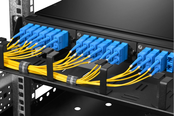
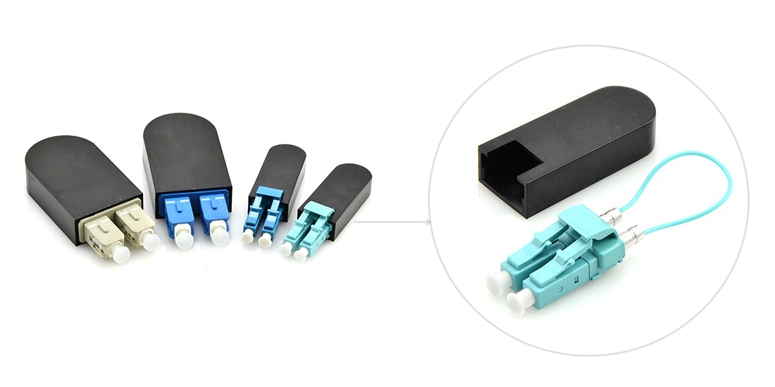
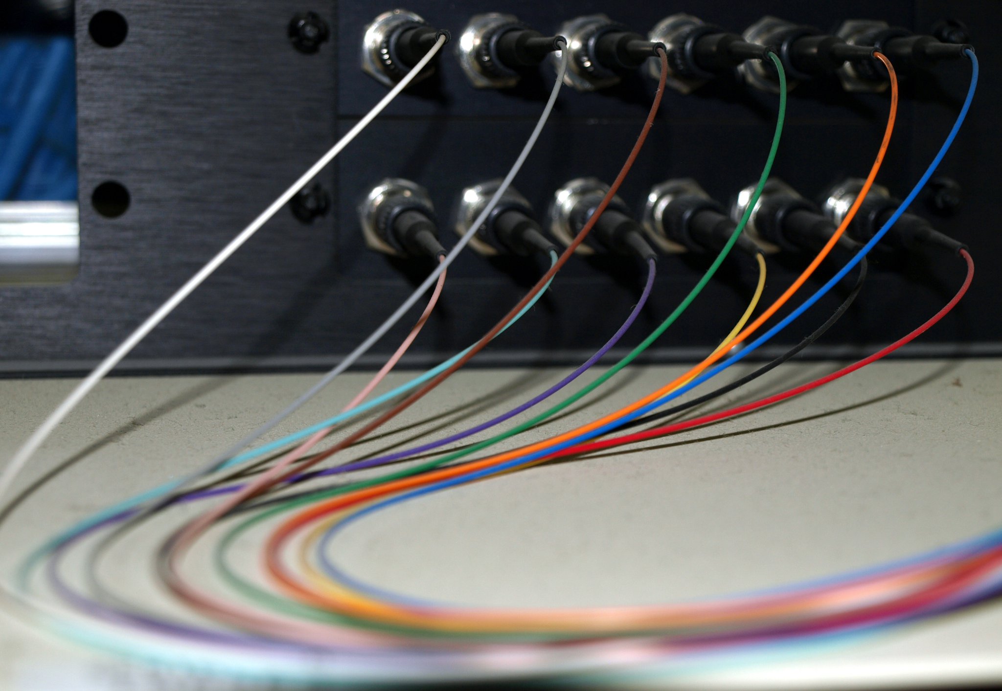
Figure: Single mode fibers are connected in a patch panel.

Single Mode Fiber Types: OS1 VS OS2

OS1 and OS2 fiber are the two single mode fiber types that are generally well known today.

What Is OS1?

OS1 is an indoor cable that uses the tight buffered cable construction. And this single mode fiber is compliant with all ITU-T G.652 standards including ITU-T G.652A, ITU-T G.652B, ITU-T G.652C, ITU-T G.652D. In general, the maximum attenuation of OS1 can achieve 1.0 dB/km.

What Is OS2?

OS2 is an outdoor loose tube fiber optic cable. It’s widely used in outdoor applications where the cabling process applies no stress to the optical cables. Unlike OS1, OS2 cables just meet the ITU-T G.652C or ITU-T G.652D standards. And the maximum attenuation of OS2 is 0.4 dB/km. Therefore, the maximum transmission distance of OS2 is much longer than that of OS1, and OS2 fiber optic cable price is higher than OS1.

OS1 VS OS2: Differences

The difference between OS1 and OS2 are quite clear. They have different construction, standards, attenuation and transmission distance. As a result, OS1 and OS2 are applied in different applications. OS1 is commonly used in a campus or data center, whereas OS2 is applied in outdoor constructions like the street etc.

How to Choose Single Mode Fiber Types

Knowing single mode fiber types can help us to choose the suitable fiber cable. Transmission distance is always the most important part when buying the cable. Besides, fiber optic cables price is also very critical when making the final choice. When you need fibers for indoors application, choose OS1. And choose OS2 for outdoors uses. However, considering that there’s not a big difference between OS1 and OS2 price and future’s network upgrade, I recommend you choose the OS2 fiber which has better performance. The following is single mode fiber optic cable price comparison between FS.COM and another vendor.

OS2 Types
FS Price(USD)
C2G(USD)
LC to LC Duplex (1m)
2.8
42.99
LC to SC Duplex (1m)
2.8
32.99
SC to SC Duplex (1m)
2.8
38.99
LC to LC Simplex (1m)
1.4
39.99
LC to SC Simplex (1m)
1.4
21.99
SC to SC Simplex (1m)
1.4
21.99

We can see, FS.COM offers OS2 fibers with reasonable price and good quality.

Conclusion

OS1 and OS2 are the two single mode fiber types used in telecommunication infrastructure. When you decide to buy single mode fiber cables, consider the transmission distance and price based on your actual need. FS.COM offers you fiber products with good quality and favorable price. For further information on optical fiber products, please contact us via sales@fs.com.

TP-Link T1700G-28TQ—An Economic Choice for SMBs

As new emerging networking standards, 40G and 100G network have been achieved initial success. But they are based on the 10G network. With the growing numbers of small business enterprises, 10G SMB switches are also in a large demand. TP-Link has introduced the T1700 Series 10G Smart Switches: the T1700X-16TS Full 10 Gigabit Smart Switch and the T1700G-28TQ Gigabit Stackable Smart Switch with 10G Uplink. They provide high levels of performance and the increased scalability that meet the requirements of SMBs. This article would introduce the T1700G-28TQ and its compatible optics.

TP-Link T1700G-28TQ Switch

As one of the TP-LINK’s Gigabit stackable smart switches, the T1700G-28TQ is able to provide reliable, cost-effective and resilient networking solutions for SMBs. The switch is equipped with 24 10/100/1000Mbps RJ-45 ports and 4 dedicated 10G SFP+ slots which can be used for uplinks and/or stacking, providing a strong interconnection between access and aggregation.

TP-Link T1700G-28TQ Switch

Figure1:TP-Link T1700G-28TQ Switch(Resource: www.TP-Link.com)

Features & Benefits of T1700G-28TQ
—Physical Stacking

The T1700G-28TQ supports rich L2 features, including 802.1Q tag VLAN, Port Isolation, Port Mirroring, STP/RSTP/MSTP, Link Aggregation Groups, and 802.3x Flow Control function. Besides, T1700G-28TQ supports L2+ feature static routing, which provides simple network segmentation by routing internal transmissions to make the ow of network traffic more efficient.

—Abundant L2 and L2+ Features

The stack system of T1700G-28TQs supports up to 40Gbps bi-directional stacking bandwidth with built-in redundancy and auto-failover. The switch supports up to 6 units in a stack, which allows it to provide up to 144 GE ports, 12 available 10G SFP+ uplinks and 768Gbps switching capacity, offering high-density developments as well as flexibility for future network expansion need.

—Secure Networking

The T1700G-28TQ supports IP-MAC-Port Binding, Port Security, Storm control, and DHCP Snooping, which help to protect the network from broadcast storms, ARP attacks, and more. And the switch supports 802.1X, which allows network clients to be authenticated through external Radius servers and the guest VLAN function allows non-802.1X clients to access specific network resources.

—Enterprise Level Management

The T1700G-28TQ is easy to use and manage. It supports various user-friendly standard management features, such as intuitive web-based Graphical User Interface (GUI), industry-standard Command Line Interface (CLI), SNMP (v1/2/3), and RMON. This allows the switch to provide valuable status information and send reports on abnormal events. Comprehensive IPv6 support management ensures a smooth migration to an IPv6-based network. It also supports Dual Image to provide improved reliability and network uptime.

Compatible Optics for TP-Link T1700G-28TQ

As being mentioned, the TP-Link T1700G-28TQ has 24 10/100/1000Mbps RJ-45 ports and 4 dedicated 10G SFP+ slots to achieve network connectivity. And it is a switch supports different optical modules and network cables. For the 10/100/1000Mbps RJ-45 ports, you can use 100BASE-TX or 1000Base-T optical transceiver with UTP category 5, 5e or above cable (maximum 100m) to achieve the link. Besides, you can also use 1000BASE-X with singlemode or multimode fiber cable to connect.

10G optics

Figure2: Optional choices for 10G network

As for the 10G SFP+ ports, there are two approaches to achieve transfer the data. You can choose 10G optical transceivers or 10G DAC cables to transfer data. The TP-Link T1700G-28TQ support 10BASE-T with UTP category 3, 4, 5 cable (maximum 100m), 10GBASE-LR and 10GBASE-SR to connect. In addition, you can use TP-LINK TXC432-CU1M or TP-LINK TXC432-CU3M to achieve the link.

The main compatible optical modules and cables are listed in the below:

  • 10BASE-T: UTP category 3, 4, 5 cable (maximum 100m)
  • 100BASE-TX/1000Base-T: UTP category 5, 5e or above cable (maximum 100m)
  • 1000BASE-X: MMF, SMF
  • 10GBASE-LR
  • 10GBASE-SR
  • TP-LINK TXC432-CU1M
  • TP-LINK TXC432-CU3M
Conclusion

TP-Link T1700G-28TQ provides cost-effective solution for 10G SMB networking. This article mainly discussed about its definition, features and benefits as well as compatible optical modules and cables. If you are looking for its compatible optical modules and cables, FS.COM is a nice choice.

CMR, CMP and LSZH MTP/MPO Cable

Multifiber MTP/MPO cable is a preferable choice for high-density telecom and datacom cabling. For the outer jacket of MTP/MPO cable, there are many terms to describe it, such as CM, LSZH, CMP, CMR, PVC, etc. FS.COM carries several of these technologies. Do you know the differences between them? And what are the characteristics of each type? Most importantly, which one do you need for the task? This post will introduce some major jacket types for MTP/MPO cable and the other acronyms for communication cable ratings.

MTP cabling

Figure 1: MTP/MPO cabling.

CMP

CMP (plenum-rated) MTP/MPO cable complies the IEC (International Electrotechnical Commission) 60332-1 flammability standard. CMP MTP/MPO cable is designed to be used in plenum spaces, where air circulation for heating and air conditioning systems can be facilitated, by providing pathways for either heated/conditioned or return airflows. Typical plenum spaces are between the structural ceiling and the drop ceiling or under a raised floor. CMP rated communication cable is suitable for telephone and computer network exactly for this matter. It is designed to restrict flame propagation no more than five feet, and to limit the amount of smoke emitted during fire. Additionally, CMP MTP/MPO cable is more fire-retardant than LSZH, and as a result, sites are better protected. As an excellent performer cable, it is usually more costly than other cable types.

It has to be noted that some CMP cable made of fluorinated ethylene polymer (FEP) still has shortcomings of potential toxicity. Thus better CMP cable with a non-halogen plenum compound is further produced. For safety reason, no high-voltage equipment is allowed in plenum space because presence of fresh air can greatly increase danger of rapid flame spreading if the equipment catch on fire.

LSZH

The LSZH (low smoke zero halogen, also refers to LSOH or LS0H or LSFH or OHLS) has no exact IEC code equivalent. The LSZH cable is based on the compliance of IEC 60754 and IEC 61034. LSZH MTP/MPO cable is better than other cables in been safer to people during a fire. It has no halogens in its composition and thus does not produce a dangerous gas/acid combination when exposed to flame. LSZH cable reduces the amount of toxic and corrosive gas emitted during inflammation. LSZH MTP/MPO cables are suitable to be used in places that is poorly aired such as aircraft, rail cars or ships, to provide better protection to people and equipment. LSZH MTP/MPO cable is more widely applied type than other materials, both for its secure properties and lower cost than CMP.

Other Types

The cable jackets will be discussed in the following part are not as frequently used for MTP/MPO cable as CMP and LSZH.

CMR (riser-rated) complies IEC 60332-3 standards. CMR cable is constructed to prevent fires from spreading floor to floor in vertical installations. It can be used when cables need to be run between floors through risers or vertical shafts. PVC is most often associated with riser-rated cable, but nor all PVC cable is necessarily riser-rated; FEP is most often associated with CMP. Since the fire requirements for CMR cable is not that strict, CMP cable can always replace CMR cable, but not reversibly.

CM (in-wall rated) cable is a general purpose type, which is used in cases where the fire code does not place any restrictions on cable type. Some examples are home or office environments for CPU to monitor connections.

The figure below generally illustrates the applicable environments for CMP, CMR and CM rated cables.

CMP, CMR, CM cable application

Figure 2: CMP, CMR, CM cable application.

Conclusion

Knowing the relevant details of cable ratings of MTP/MPO will certainly help in selecting the best one for your applications, which is as important as other factors. FS.COM provides high quality plenum and LSZH MTP/MPO trunk cables and MTP breakout cables at affordable prices.

Which Fiber Loopback Should I Use for My Transceiver?

In telecommunication, fiber loopback is a hardware designed to provide a media of return patch for a fiber optic signal, which is typically used for fiber optic testing or network restorations. When we need to know whether our fiber optic transceiver is working perfectly, we can use a fiber loopback cable as an economic way to check and ensure it. Basically, the loopback aids in debugging the physical connection problem of the transceiver by directly routing the laser signal from the transmitter port back to the receiver port. Since fiber optic transceivers have different interface types and connect different types of cables, it is not that simple to choose a right loopback for our transceiver. This post will be a guide on how to choose a right loopback cable for specific transceiver module.

Fiber Loopback Types and Configurations

Before deciding which loopback cable to use, we should firstly know the structure and classification of fiber loopback cable. Generally, a fiber loopback is a simplex fiber optic cable terminated with two connectors on each end, forming a loop. Some vendors provide improved structure with a black enclosure to protect the optical cable. This designing is more compact in size and stronger in use. Based on the fiber type used, there is single-mode loopback and multimode loopback, available for different polishing types. According to the optical connector type of the loopback, fiber loopback cables can be divided to LC, SC, FC, ST, MTP/MPO, E2000, etc. In testing fiber optic transceiver modules, the most commonly used are LC, SC and MTP/MPO loopback cables.

lc&sc loopback cable
Figure 1: LC & SC Loopback Cable

The LC and SC loopbacks are made with simplex fiber cable and common connectors; it’s not difficult to understand their configurations. As for the MTP/MPO loopback, it is mainly used for testing parallel optics, such as 40G and 100G transceivers. Its configuration varies since the fiber count is not always the same in different applications.

8 Fibers MTP/MPO Loopback Cable Configuration

In a 8 fibers MTP/MPO loopback, eight fibers are aligned on two sides of the connector, leaving the central four channels empty. And the fibers adopt a straight configuration of 1-12, 2-11, 5-8, 6-7. The polarity channel alignment is illustrated in the following figure.

8 Fibers Loopback Polarity Channel Alignment
Figure 2: 8 Fibers Loopback Polarity Channel Alignment
12 Fibers MTP/MPO Loopback Cable Configuration

The only difference between the 12-fiber MTP loopback and the 8-fiber loopback is that the central four channels are not empty. Its alignment is 1-12, 2-11, 3-10, 4-9, 5-8, 6-7.

12 Fibers Loopback Polarity Channel Alignment
Figure 3: 12 Fibers Loopback Polarity Channel Alignment
24 Fibers MTP/MPO Loopback Cable Configuration

The 24 fibers MTP loopback also adopts type 1 polarity. Its alignment design is shown below.

24 Fibers Loopback Polarity Channel Alignment
Figure 4: 24 Fibers Loopback Polarity Channel Alignment
Which to Choose for a Specific Transceiver?

Considering the common features of the transceiver and the loopback, we should think about the connector type, polish type, and cable type when selecting a loopback for the transceiver. The selection guide for some mostly used transceiver modules is summarized in the following tables.

Table 1: Loopback choices for 10G SFP+ transceivers

Model Interface type Cable Type Suited Loopback
10GBASE-USR LC Duplex (PC) MMF

LC/UPC Duplex Multimode Fiber Loopback

10GBASE-SR LC Duplex (UPC) MMF
10GBASE-LR LC Duplex (UPC) MMF
10GBASE-ER LC Duplex (UPC) SMF

LC/UPC Duplex Single-mode Fiber Loopback

10GBASE-ZR LC Duplex (PC) SMF

Table 2: Loopback choices for 40G QSFP+ transceivers

Model Interface type Cable Type Suited Loopback
40GBASE-CSR4 MTP/MPO (UPC) MMF

8/12 Fibers MTP/UPC Multimode Fiber Loopback

40GBASE-SR4 MTP/MPO (UPC) MMF
40GBASE-PLRL4 MTP/MPO (APC) SMF

8/12 Fibers MTP/APC Single-mode Fiber Loopback

40GBASE-PLR4 MTP/MPO (APC) SMF
40GBASE-LR4 LC Duplex (PC) SMF

LC/UPC Duplex Single-mode Fiber Loopback

40GBASE-LR4L LC Duplex (UPC) SMF
40GBASE-ER4 LC Duplex (UPC) SMF
40GBASE-LX4 LC Duplex (UPC) MMF/SMF

LC/UPC Duplex Multimode/Single-mode Fiber Loopback

Table 3: Loopback choices for 100G QSFP28 transceivers

Model Interface type Cable Type Suited Loopback
100GBASE-SR4 MTP/MPO (UPC) MMF

8/12 Fibers MTP/UPC Multimode Fiber Loopback

100GBASE-PSM4 MTP/MPO (APC) SMF

8/12 Fibers MTP/APC Single-mode Fiber Loopback

100GBASE-LR4 LC Duplex (UPC) SMF

LC/UPC Duplex Single-mode Fiber Loopback

Table 4: Loopback choices for CFP transceivers

Model Interface type Cable Type Suited Loopback
40GBASE-SR4 CFP MPO/MTP (UPC) MMF

8/12 Fibers MTP/UPC Multimode Fiber Loopback

40GBASE-LR4 CFP SC Duplex (UPC) SMF

SC/UPC Duplex Single-mode Fiber Loopback

40GBASE-FR CFP SC Duplex (UPC) SMF
100GBASE-LR4 CFP SC Duplex(PC/UPC) SMF
100GBASE-ER4 CFP SC Duplex(PC/UPC) SMF
100GBASE-SR4 CFP MPO/MTP (UPC) MMF

24 Fibers MTP/UPC Multimode Fiber Loopback

Conclusion

This post discusses specific fiber loopback choices for some most commonly used fiber optic transceivers. For other transceiver modules that are not mentioned in this post, we can also know how to choose a suitable loopback for it by getting details about its interface type, physical contact and cable type.

Importance of Using Fiber Color Codes in Data Center

The utilization of fiber color code in data center effectively helps technicians make better cable management and reduce human errors. Without redundant checking process, people can easily get the information of the device by only one look. Making good use of the color code system can surely save much time during work. This article will mainly present the widely accepted color code system and its important functions.

fiber color code

Introduction to Fiber Color Code Systems

Fibers, tubes and ribbons in fiber optic cables are usually marked with different color codes to facilitate identification. There are many color code systems for national or international use. All these systems are characterized by using 12 different colors to identify fibers that are grouped together in a common bundle such as a tube, ribbon, yarn wrapped bundle or other types of bundle.

Different color code standards may be used in different regions. For example, the S12 standard is used for micro cables and nano cables in Sweden and other countries. The Type E standard is defined by Televerket and Ericsson used in Sweden. The FIN2012 standard is used in Finland, etc. However, there is one color code system widely recognized in the world, namely the TIA/EIA-598 standard.

Specifications of TIA/EIA-598 Color Codes

The following picture gives the fiber color coding of TIA/EIA-598 standard. If more than 12 fibers or tubes are to be separated, the color sequence is normally repeated with ring marks or lines on the colored fibers and tubes. As for the fiber cable jacket, orange, yellow, aqua and black color codes are used for their distinction.

color-code-system

Functions of Fiber Color Code in Data Center
Distinguishing Fiber Grades

As mentioned above, the outer jacket color codes are able to identify the fiber grades. OM1/OM2 cables often adopt the orange jacket, OM3/OM4 cables with aqua jacket, single-mode cables with yellow jacket and hybrid cables (indoor/outdoor cables and outside plant cables) with black jacket. One thing to note is that the mix of OM1 and OM2 or OM3 and OM4 cables may be troublesome. You should make sure not to mingle these cables with the same color code.

Identifying Fiber Patch Cords

Using fiber color code to label fiber patch cords can reduce the potential for human error. For instance, you may highlight mission-critical patch cords in red, and then teach all technicians that a red patch cord should only be moved with proper authorization or under supervision. Likewise, keeping the fiber connector color consistent with fiber grade color standards will make it simple for technicians to use the right connectors with the cables.

Separating Different Ports

The color-coded port icons can be helpful in identifying different network routings in accordance with internal needs. By tagging each patch panel port, you can simplify and streamline network management.

Differentiating Connector Boots

You can use fiber color code on connector boots to make routine maintenance and moves, adds and changes easier by helping technicians preserve correct parallel groupings for switch ports. If you change your connector color, you need to ensure that your fiber cable color represents the fiber grade to avoid confusion. You can also change the color of a connector boot to differentiate between different aspects of the network, making it easy for technicians to view the contrast within a panel.

Conclusion

Visual management is more intuitive for specialists to supervise the data center. Color code system has provided an ideal and easy way to solve the cabling problem. Inside the cables, the fiber buffers are also color-coded with standard colors to make connections and splices easier. Therefore, if you are still bothered by these issues of fiber patch cables, using the fiber color code system is a good way to go.

Related Articles:
How to Identify the Color Codes?
Fiber Patch Panel Color Codes