Fiber Optic Cables Installer Guidance

Nowadays, data transfer is among the most significant task to be accomplished by a data developer. There are numerous data transfer methods available in the market, but they are not reliable and safe. These reliability and security issues have caused lots of problems to those who need the data in its original form. However, you’ve fiber optic cables now.

Fiber optic cables are the most dependable and elegant approach to transfer data in the field. They set a standard, which may be hardly reached by other cables. It can possess a signal with highest efficiency, since the signal in a very fiber optic cable isn’t getting that much attenuated, at a least signal loss.

Furthermore, unlike copper wires, fiber optic cables don’t let intrusion of outdoor signals. In order to mix or access the signal carried from the fiber optics, one must intervene physically, which cannot go undetected without correct surveillance equipment. Therefore, fiber optic cabling is several folds securer compared to the regular copper cables. Also, since fiber optics isn’t made of copper wire or any other metallic wires, it’s much less denser, thus which makes it convenient to carry around and also needs fewer personnel for installing. Nevertheless, the cost of fiber optic cable might be a little higher than the regular cables, but studying the advantages and sum of money trapped in its maintenance and functioning accocunts for much more than the fee incurred.

With proper installation of fiber optic cables, the info could be delivered to more than a 1000 kilometers distance however, if the cables aren’t installed since they ought to be, then the data may well not even visit a person sitting beside the sender. For the effective usage of fiber optic cables, the installer should become aware of the policies information required.

Now the fundamental question that arises is the fact that the thing that makes the use of fiber optics installer effective? The answer is the data concerning the types of fiber optics and their installation this includes the techniques of protecting these cables in numerous environmental conditions. Fiber optic cables are designed to be able to minimizing the worries caused to the cable i.e., temporary or long-term stress and in addition to that, there should be fire safety compliance with in the cable. All these efforts assembled to style a fiber optic cable are effective only if the cable is installed properly by using the fiber optics installer guide.

There are lots of fiber optic cables which are manufactured as reported by the dependence on their usages which categorizes them into 2 types which can be maximum tensile strength and minimum bend radius. These optical cables which can be manufactured for special purposes as well as need special type of skills and their installation needs to be followed as per the manufacturers’ specifications for their proper and effective working. Moreover, from your manufacturing types, the fiber optic cables can be categorized into indoor fiber optic cables and outdoor fiber optic cables. These two differ from their manufacturing aspects and different features will also be added to them. The fiber optic cables useful for the great outdoors possess a rugged outer body and less flexibility in order to withstand the outdoor harsh temperature and environment whereas the indoor fiber optic cables have a flexible and fewer rugged cover. These two cables need different kinds of fiber optics installer guidance to put in.

Technology is incredibly dependent on its sources and fiber optic cables are among the most dependable sources. Nevertheless the users must remember the different types of cables, the manufacturing, cellular phone and structure which may be done using a fiber optics installer guide.

Fiber optics installer guidance is indeed important, where can users get the right suitable guidance for installation? Generally, fiber optics installer guidance could be a paper manual with all the fiber optic cable installation tools. However, installing different type of cable comes to a different guidance, such as installing Cat 7 cable is different from that of MPO to LC cable.

Fiber Optic Cleaver Needed In Fiber Optic Cleaving

If you have never done cable splicing and are just beginning to build your fiber optic link, it is recommended to start out with our fiber splicing kit, which is a great starting point for your fiber installation.

Optical fiber fusion splicing always requires that the fiber tips have a smooth end face that is perpendicular to the fiber axis. The cleave quality is very important in determining the fusion splicing loss. This is especially true for specialty fibers such as erbium-doped fibers and dispersion-compensating fibers.

Fiber optic cleaving is the process to scribe and break an optical fiber endface. Fiber optic technicians need some training in order to gain the skills necessary for best possible results.

The goal of fiber cleaving is to produce a mirror like fiber endface for fiber splicing – either fusion splicing or mechanical fiber splicing. Incorrect or pool cleaving techniques will result in lips and hackles which makes good fiber splicing impossible. A bad cleaving usually has to be redone.

The tools needed for fiber cleaving are called fiber optic cleaver or fiber cleave tools. There are two types available on the market: high precision fiber cleaver and field fiber cleaver.

The design of fiber optic cleavers varies among manufacturers such as AFL, Corning, Fujikura or York. But the working principle is the same. Here I describe a typical work flow of optical fiber cleavers.

Step One: Strip the fiber to its cladding size, the standard optical fiber cladding size is 125um. The strip length depends on your application.

Step Two: Clean the fiber with lint-free wipes moistened with isopropyl alcohol.

Step Three: Place the stripped and cleaned bare fiber into the fiber cleaver

Step Four: Scribe the bare fiber with either a cutting wheel or a blade

Step Five: Break the fiber with the built-in mechanism on the cleaver

Step Six: Remove the fiber scrap and put it into a fiber disposal unit

This semi-automated process produces high quality cleaving in minimum steps. It has been used widely in the fiber optic communication industry.

FiberStore provides a complete line of cables, connectors, termination tools, and test equipments for installing and testing fiber optic network. It’s important to make sure you have the proper set of fiber optic tools to working with your fiber optics. At FiberStore, they carry a wide selection of fiber tools, just about every tool needed to successfully install, terminate and test the fiber you’ve installed. Some of the essential fiber tools to have would be a fiber tester, fiber stripper, telephone line tester, fiber optic cleaver, tool kits and other tools.

Using Underground Tracer Wire to Locate Buried Cable

Underground tracer wire is designed to locate the underground pipes after they are buried, which are required by many building codes for the gas and sewer lines into buildings. When first introduced, it needed to do little more than find buried water, gas, or sewer lines. Today, locating has become more complex as telecommunications cables joint utility lines in the underground environment. Fortunately, today’s underground fiber optic cable locator relies on the same basic technology found in their early counterparts – injecting an electrical signal onto the cable being located.

Underground Cable Locator

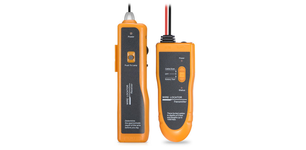
Underground cable locator is a commonly uesd underground fiber optic cable locator, which consists of two parts – a transmitter and a receiver. The transmitter puts an electrical signal onto the cable or pipe being traced, while the receiver picks up the signal, allowing the locator operator to trace the signal’s patch and follow the cable being located.

underground fiber optic cable locator

How to Use Underground Fiber Optic Cable Locator

Installing a tracer wire creates a safer work environment for excavators or homeowners in the future. Make sure to leave several inches of tracer wire above ground for future use. See the details on how to install underground tracer wire:

Holder the tracer wire at the start of the pipe near the street and fasten it to the pipe by wrapping it with electrical tape.

Roll up the tracer wire along the pipe, taping it to the pipe every 5 feet.
Run the wire up the pipe to the point where it exits above finished grade. Cut the wire so there is 6 to 12 inches of wire above the ground.
Fasten the wire close to the end of the pipe to ensure it is visible for future use.

Tracing buried cables is a relatively simple procedure that comes in handy in outside-plant environments, where you need to know the location of a cable before the backbone rips up earth near the buried cable. Locators can also find the problem-stricken telecommunications cables. What sets these tools apart from their inside-plant counterparts is that they need to be able to differentiate the target cable from other nearby cables and underground utilities and provide an estimate of depth.

Conclusion

Since locating underground fiber optic cable has taken on increasing significance in recent years as more and more fiber cable has been buried underground, many fiber optic cable manufacturers have begun providing these products. FS provides customers the good quality products with low price. Any question about testing cables, please contact us via sales@fs.com.

Related Articles:
Anatomy of Underground Cable Locator
Tight-Buffered Fiber Distribution Cable for Indoor and Outdoor Use

Ethernet And Fiber Optic Cabling

Even in the age of WiFi and high speed cellular networks, we still need networking cables to together our computing hardware together. Both Ethernet cables and fiber optic cables are used to deliver and distribute communications. Offering a fast, secure and reliable connection, these cables play different roles in delivering critical entertainment and business data.

Ethernet Cable
Originally developed by Xerox in the 1970s, Category 5 and 6 cables, or Cat 7 cable connect computers and gaming systems to routers in our homes and offices. Recognized by their large locking RJ45 plastic connectors and resembling over-sized phone wires, these cables carry data measured in the hundreds of megabits per second. These multi-conductor cables also connect routers to modems and switches, depending on a network’s configuration.

Ethernet data rates vary depending on the cable used. The newest Cat 7 cable, 10 Gigabit Ethernet, transmits up to 10 Gbps. Category 7 technology improves both internal signaling and exterior shielding compared to older CAT5 / CAT5e and CAT6 cables. CAT 7 cable supports 10 Gigabit Ethernet network connections, and CAT7 cables are also compatible with standard Ethernet adapters.Gigabit Ethernet transmits up to 1 Gbps. Fast Ethernet, still the most common cable used in homes and offices today, transmits up to 100 Mbps (approximately 0.1 Gbps).

Fiber Optic Cable
Fiber optic cable’s primary claim to fame is its ability to carry vast amounts of data over considerable distances. Fiber optic wiring is normally found leading from an Internet service provider’s central distribution center to individual localized hubs in a neighborhood. Amazingly, this data is carried along glass or plastic fibers as light. Depending on whether the Internet service is DSL or cable-based, phone wires or coaxial cable then lead to each address. Fiber optic cable retrofits have enabled service providers to offer higher speeds and increased data throughput. Signals on fiber optic cables are typically repeated or boosted to compensate for signal losses over distance.

At distances up to 1.86 miles, single-mode fiber-optic cable can transmit data up to 10 Gbps, but it is used primarily for video. It is used primarily for high-bandwidth video or as a backbone to connect networks between buildings. Multimode fiber, which is used for voice, data, and video, has a data rate up to 1 Gigabit per second for distances under 1.24 miles.

Multifiber Push-On (“MPO”) fiber trunks (like MPO to LC cable) have become the default cabling solution to these ever-increasing data center bandwidth requirements. Because they are a natural fit for parallel optics, these fiber links are compact, pre-terminated, able to handle bandwidth all the way up to 100 Gbps, and even plug and play by design.

People always think fiber optic cable would beat copper Ethernet cable hands down. However, cable manufacturers have continued to update the technology behind Ethernet, meaning it can be just as fast as some fiber optic cables today. For example, Cat 7 cable is a next-generation standard cabling technology transmits up to 10 Gbps. While Ethernet cable and fiber optic cable are completely different, fiber optic cable can be used in Ethernet networks. Ehernet cable price and fiber optic cable price are also not the same, choosing Ethernet cable or fiber optic cable you should take it into consideration.

WDM Technology

After languishing for many years as an interesting technology without a cost-effective application, wavelength-division multiplexing started playing a major role in telecommunications networks in the early 1990s, This resulted from the surge in demand for high-capacity links and the limitation of the installed fiber plant in handling high-rate optical signals over any substantial distance.

This limitation led to a rapid capacity exhaustion of long-haul fiber networks.
While installing an optical fiber cable plant is both expensive and extremely time consuming, expanding the capacity of an installed network is economically attractive. Tradition carries upgraded their link capacity by increasing the transmission rate. This worked well initially, with speeds eventually reaching 2.5 Gb/s. However, when going to the next multiplexing level of 10Gb/s, people starts to encounter the effects that can seriously degrade WDM network performance such as the dispersion, reflections, scattering, etc.

New fiber designs, special dispersion-compensation techniques, and optical isolators can mitigate these limitations, and newly installed links are operating very well as 10Gb/s per wavelength.

However, a large portion of the older installed fiber base is limited to OC-48 rates (2.5Gb/s) at a given wavelength. Thus, a great interest has been established in using WDM, not only for older links but also to have a very high capacity new links.

For a typical WDM link. At the transmitting end, there are several independently modulated light sources, each emitting signals at a unique wavelength. Here a multiplexer is needed to combine these optical outputs into a continuous spectrum of signals and couple them onto a single fiber. At the receiving end, a demultiplexer is required to separate the optical signals into appropriate detection channels for signal processing. At the transmitter, the basic design challenge is to have the multiplexer provide a low-loss path from each optical source to the multiplexer output. Since the optical signals that are combined generally do not emit any significant amount of optical power outside of the designated channel spectral width, interchannel cross-talk factors are relatively unimportant at the transmitting end.

WDM Multiplexers
Wavelength multiplexers are specialized devices that combine a number of optical streams at distinct wavelengths and launch all their powers in parallel into a single fiber channel. This
combination need not be uniform for all wavelengths; that is. One may want to combine 50% of the power from on wavelength, 75% from another source, and 100% from other wavelengths. However, for WDM applications it is usually desirable that the multiplexers combine the optical powers from multiple wavelengths onto a single fiber with little loss. Wavelength demultiplexers divide a composite multichannel optical signal into different output fibers according to wavelength without splitting loss. This section describes a phased-array-based WDM multiplexer and a fiber-grating multiplexer as examples of such components.