With the growth of today’s network, the amount of hardware involved has become a barrier to efficient and optimized network operations. In some cases, a fiber switch is the answer. These fiber switches with management functions can reduce the burden on the network backbone, by connecting different edge-level devices and combining them into a single data stream. Today, we’ll focus on SFP fiber switch and its cabling solutions.
SFP Fiber Switch Introduction
As the name implies, an SFP fiber switch is a communication control device with SFP ports. And like a common networking switch, SFP fiber switch is also used to send and receive data transmission, but in fiber channel. These SFP ports are small form-factor hot pluggable interfaces, so the SFP optical transceiver modules can be inserted into the SFP ports. Then the fiber cables can be used to connect the fiber switch to other networking equipment.
Advantages of SFP Fiber Switch
SFP fiber switch can provide a higher reliability and security than the RJ45 port switch. As we know, fiber cables transfer data in light, which is faster than the copper cables’ electronic transmission speed. And due to the special design of fibers, the SFP fiber switch generates less data loss and electromagnetic interference. Therefore, using an SFP fiber switch is better than the RJ45 port copper switch. For example, if the transmitting distance is more than 100 meters, copper cables like Cat5e or Cat6a is unable to reach. So you need the fiber cables which are often used to interconnect switches in multi-building deployments.
FS SFP Fiber Switch Cabling Solution
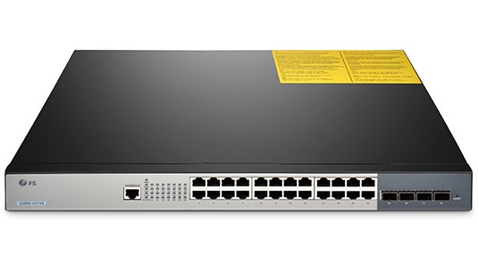
To meet the market demands, FS.COM has published a set of fiber switches and the corresponding cabling solutions. Here we take S5800-48F4S SFP fiber switch as an example. Before we learn its cabling solutions, let’s have a look at the fiber switch first.
This SFP network switch is a 10GbE switch. It’ s designed with 48 1GbE SFP ports and 4 10GbE SFP+ ports, which allows high performance routing, host and access protocol emulation. With the latency of 2.3us and switching capacity of 176Gbps, this Layer 3 switch is a great option for data centers. Its body is compact and made of sturdy material that complies with ISO9001, ETL, CE, FCC standards. The following video shows the cabling solutions between S5800-48F4S switch and other switches.
As the video shows, a completed cabling solution of a fiber switch includes transceiver and fiber cables. Here S5800-48F4S switch can support 1G SFP, 1GBASE-T and 10G SFP+ transceivers. So we list some supported transceivers as shown in table 1 for your reference.
|
Transceiver ID
|
Description
|
Price (US dollars)
|
|
1000BASE-T SFP Copper RJ-45 100m Transceiver Module
|
$21
|
|
|
1000BASE-SX SFP 850nm 550m DOM Transceiver Module
|
$6
|
|
|
1000BASE-EX SFP 1310nm 40km DOM Transceiver Module
|
$14
|
|
|
1000BASE-EX SFP 1550nm 40km DOM Transceiver Module
|
$24
|
|
|
1000BASE-ZX SFP 1550nm 80km DOM Transceiver Module
|
$24
|
|
|
10GBASE-SR SFP+ 850nm 300m DOM Transceiver Module
|
$16
|
|
|
10GBASE-LR SFP+ 1310nm 10km DOM Transceiver Module
|
$34
|
Table 1
The following table 2 are the supported cables that can be used for connecting S5800-48F4S switch to other networking equipment.
|
Fiber ID
|
Fiber Connector
|
Fiber Mode
|
1M Price (US dollars)
|
|
Unshielded
|
Cat6
|
$1.7
|
|
|
Unshielded
|
Cat6
|
$1.7
|
|
|
LC UPC to LC UPC
|
OM4 50/125μm
|
$6.6
|
|
|
LC UPC to LC UPC
|
OM4 50/125μm
|
$4.5
|
|
|
LC-LC
|
OS2 SMF
|
$11
|
|
|
LC-LC
|
SMF 9/125μm
|
$8.4
|
Table 2
Conclusion
SFP fiber switch can actually improve overall speeds and responsiveness of one’s network. FS carries a full line of Gigabit Ethernet switch, including 8 port SFP fiber switch, 24 or 48 port fiber switch. Contact us via sales@fs.com for a free consultation on your networking needs and choose the suitable fiber switch based on your specific requirement.