
Since we have discussed connectivity solutions for two duplex optics or two parallel optics in the last post (see previous post: Connectivity Solutions for Duplex and Parallel Optics), the connectivity solutions for parallel to duplex optics will be discussed in this article, including 8-fiber to 2-fiber, and 20-fiber to 2-fiber.
When directly connecting one 8-fiber transceiver to four duplex transceivers, an 8-fiber MTP to duplex LC harness cable is needed. The harness will have four LC duplex connectors and the fibers will be paired in a specific way, assuring the proper polarity is maintained. This solution is suggested only for short distance within a given row or in the same rack/cabinet.

Figure 1: 8-fiber to 2-fiber direct connectivity
This is an 8-fiber to 2-fiber interconnect. The solution in figure 2 allows for patching on both ends of the fiber optic link. The devices used in this link are recorded in the table below figure 2.
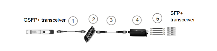
Figure 2: 8-fiber to 2-fiber interconnect
| Item | Description |
| 1 | 8 fibers MTP trunk cable (not pinned to pinned) |
| 2 | 96 fibers MTP adapter panel (8 ports) |
| 3 | 8 fibers MTP trunk cable (not pinned) |
| 4 | MTP-8 to duplex LC breakout module (pinned) |
| 5 | LC to LC duplex patch cable (SMF/MMF) |
Figure 3 is also an interconnect for 8-fiber parallel QSFP+ to 2-fiber SFP+. This solution is an easy way for migration from 2-fiber to 8-fiber, but it has disadvantage that the flexibility of the SFP+ end is lacked because the SFP+ ports have to be located on the same chassis.
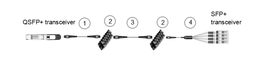
Figure 3: 8-fiber to 2-fiber interconnect
| Item | Description |
| 1 | 8 fibers MTP trunk cable (not pinned to pinned) |
| 2 | 96 fibers MTP adapter panel (8 ports) |
| 3 | 8 fibers MTP trunk cable (not pinned) |
| 4 | 8 fibers MTP (pinned) to duplex 4 x LC harness cable |
Figure 4 shows how to take a 20-fiber CFP and break it out to ten 2-fiber SFP+ transceivers. The breakout modules divide the twenty fibers into three groups, and ten LC duplex cables are used to accomplish the connectivity to SFP+ modules.
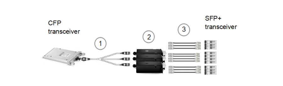
Figure 4: 20-fiber to 2-fiber interconnect
| Item | Description |
| 1 | 1×3 MTP breakout harness cable(24-fiber MTP to three 8-fiber MTP) (not pinned) |
| 2 | MTP-8 to duplex LC breakout module (pinned) |
| 3 | LC to LC duplex cable (SMF/MMF) |
There are two cross-connect solutions for 8-fiber parallel to 2-fiber duplex. The main difference for figure 5 and 6 is on the QSFP+ side. The second cross-connect is better for a greater distance between distribution areas where the trunk cables need to be protected from damage in a tray.
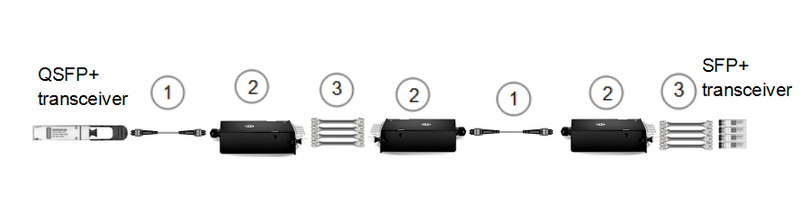
Figure 5: 8-fiber to 2-fiber cross-connect (1)
| Item | Description |
| 1 | 8 fibers MTP trunk cable (not pinned) |
| 2 | MTP-8 to duplex LC breakout module (pinned) |
| 3 | LC to LC duplex cable (SMF/MMF) |
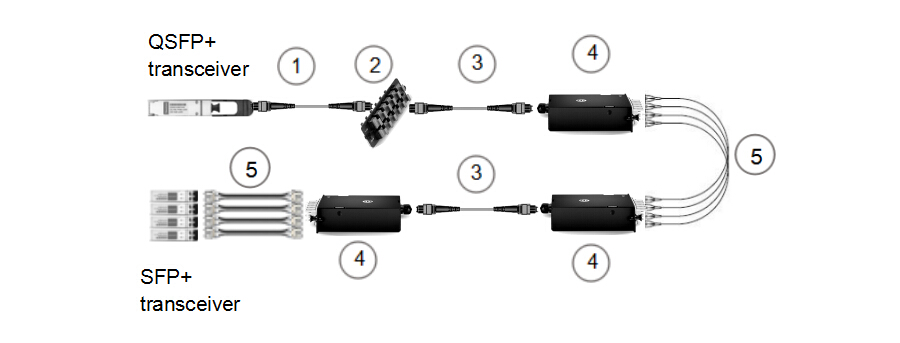
Figure 6: 8-fiber to 2-fiber cross-connect (2)
| Item | Description |
| 1 | 8 fibers MTP trunk cable (not pinned to pinned) |
| 2 | 96 fibers MTP adapter panel (8 ports) |
| 3 | 8 fiber MTP trunk cable (not pinned) |
| 4 | MTP-8 to duplex LC breakout module (pinned) |
| 5 | LC to LC duplex cable (SMF/MMF) |
These solutions are simple explanations to duplex and parallel optical links. It seems that the difference between each solution is not that significant in plain drawing, but actually the requirements for components are essential to an efficient fiber optic network infrastructure in different situations. Whether it is a narrow-space data center or a long-haul distribution network that will mostly determine the cabling structure and the products used.