Choosing the correct unmanaged switch is crucial for establishing a dependable and cost-effective network infrastructure. In contrast to managed switches, unmanaged switches are plug-and-play devices that require no manual configuration or network monitoring. They provide simplicity and ease of use, making them ideal for SMEs with limited IT resources. FS S1900 series switches are unmanaged switches and are worthy of your choice
Features and Benefits
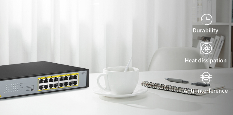
Metal Enclosure
The metal-cased unmanaged switch provides superior durability, heat dissipation, and resistance to interference compared to their plastic counterparts. With a metal enclosure, these switches offer protection for internal electronic components, shielding them from external impacts and physical damage, thus contributing to enhanced stability and reliability. Furthermore, the excellent heat dissipation properties enable efficient absorption and conduction of heat, ensuring that the switch remains within a safe temperature range, thereby mitigating the risk of performance degradation or failure caused by overheating. Moreover, the metal shell exhibits a shielding effect against external interference signals, effectively minimizing the impact of electromagnetic interference and delivering a more stable and dependable network connection.
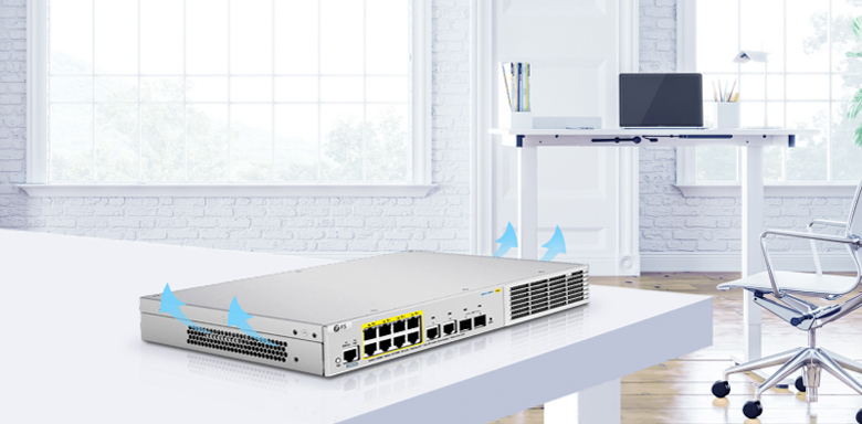
Fan and Fanless
Switches with fans provide improved heat dissipation capabilities, effectively absorbing and dissipating heat to maintain a safe operating temperature. The presence of fans enables these switches to handle higher processing power and throughput, efficiently managing heavier data traffic and network loads.
On the other hand, fanless switches utilize a passive cooling design, eliminating noise generated by mechanical operation. They rely on passive cooling methods and minimize the use of mechanical components, resulting in enhanced reliability and stability. These switches are well-suited for noise-sensitive environments such as offices, conference rooms, or quiet computer rooms. Fanless switches do not require additional cooling mechanisms, resulting in lower power consumption, energy savings, and reduced environmental impact.

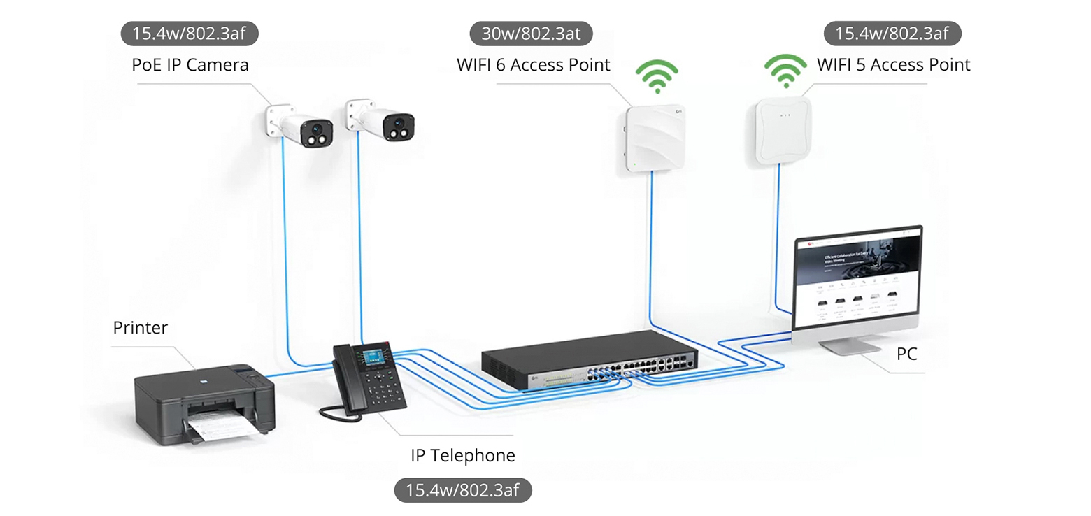
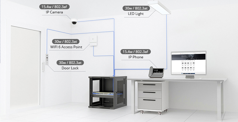
PoE and Non-PoE
Non-PoE switches have lower power consumption compared to PoE switches since they do not need to provide power to PoE devices. On the other hand, PoE switches are designed to supply power to PoE devices such as IP phones, wireless access points, cameras, etc., through network cables. As a result, PoE switches typically consume more power than non-PoE switches to meet the additional power requirements. Power consumption may also vary depending on the specific PoE standards, as different standards correspond to different power output capabilities. Whether you need PoE or not, FS has an unmanaged switch to meet your needs.
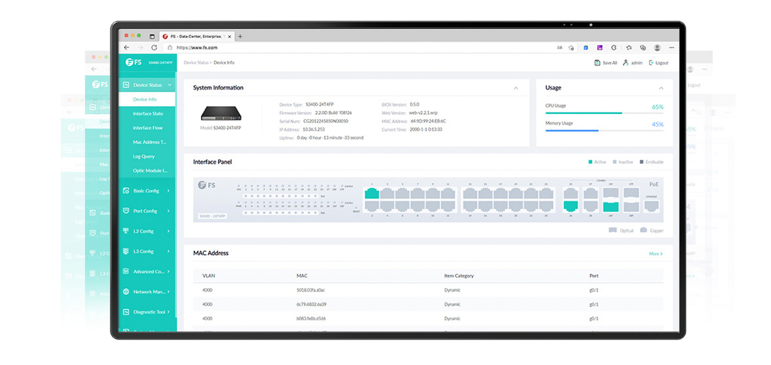
Unmanaged Functions
Unmanaged switches are relatively simple and plug-and-play devices. They have port adaptation functions that can automatically adjust to different rates (such as 10Mbps, 100Mbps, 1Gbps, etc.) according to the connected devices. Additionally, they can filter packets based on the destination MAC address, ensuring that only the destination device receives forwarded packets. This feature not only enhances network performance but also helps improve security.
Unmanaged switches recommended
FS S1900 series offers a wide range of reliable and cost-effective unmanaged switches suitable for SMBs. Here are some top recommendations:
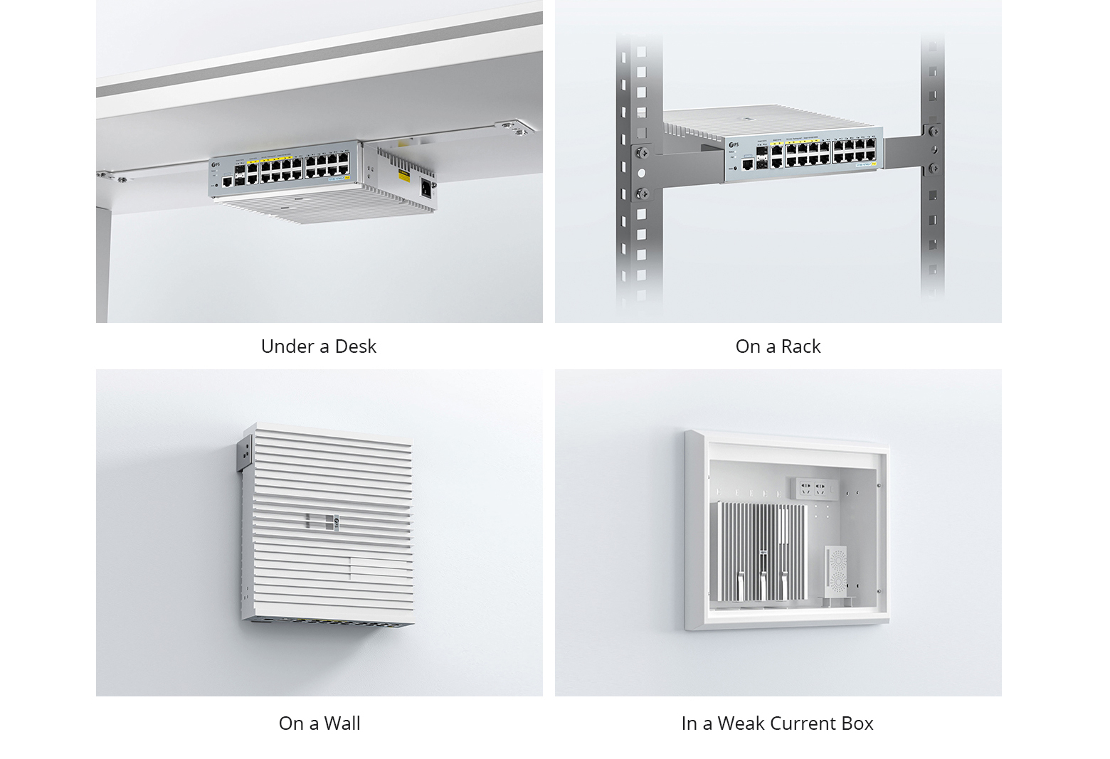
| RJ45 Ports | PoE Ports | Fan | Mounting Options | IEEE 802.3az (EEE) | |
| S1900-5T | 5x 10/100/1000BASE-T RJ45 | No | Fanless | Desktop and Wall Mount | √ |
| S1900-5TP | 5x 10/100/1000BASE-T RJ45 | 4x PoE+ | Fanless | Desktop and Wall Mount | √ |
| S1900-8T | 8x 10/100/1000BASE-T | No | Fanless | Desktop and Wall Mount | √ |
| S1900-8TP | 8x 10/100/1000BASE-T RJ45 | 8x PoE+ | 1 Built-in | Desktop and Rackmount | √ |
| S1900-16T | 16x 10/100/1000BASE-T | No | Fanless | Desktop and Wall Mount | × |
| S1900-16TP | 16x 10/100/1000BASE-T RJ45 | 16x PoE+ | Fanless | Desktop and Rack Mount | × |
| S1900-24T | 24x 10/100/1000BASE-T | No | Fanless | Desktop and Rack Mount | × |
Conclusion
An unmanaged switch is a fundamental, no-frills networking device. They require no configuration, and they’re inexpensive enough to be used for small networks. For smaller networks and for certain dedicated applications, unmanaged Ethernet switches are an economical alternative to managed and web-smart Ethernet switches. Choose unmanaged switches, and you can trust the quality of FS.
Related Articles:
Managed vs Unmanaged Switch: Which One Can Fit Your Real Need?
12-Port SFP+ Managed Switch S5800-8TF12S for SMB Hyper-Converged Infrastructure