In the realm of network communications, the increasing demands for data processing have posed a challenging task for many enterprises: integrating high-speed, stable, and flexible data transmission solutions. This article will explore a solution that not only addresses the requirements of modern data centres but also considers cost efficiency—dual rate 10/25G transceiver module. With its versatility and economic viability, the dual rate module signifies a strategic amalgamation of performance and scalability ideally suited for the evolving landscape of network infrastructure.
What is Dual Rate 10/25G Transceiver Module?
The dual rate 10/25G transceiver module is a form of optical transceiver capable of accommodating two distinct data rate options: 10 gigabits per second (Gbps) and 25 Gbps. Its design allows seamless interoperability with network equipment, dynamically adjusting between these speeds based on the connected devices’ capabilities and the network’s requirements.
These dual rate modules provide a high level of flexibility for network infrastructure, eliminating the need for multiple types of transceivers. This significantly simplifies the management of network upgrades and inventory, as the same module can be employed across various network segments operating at either 10Gbps or 25Gbps speeds.
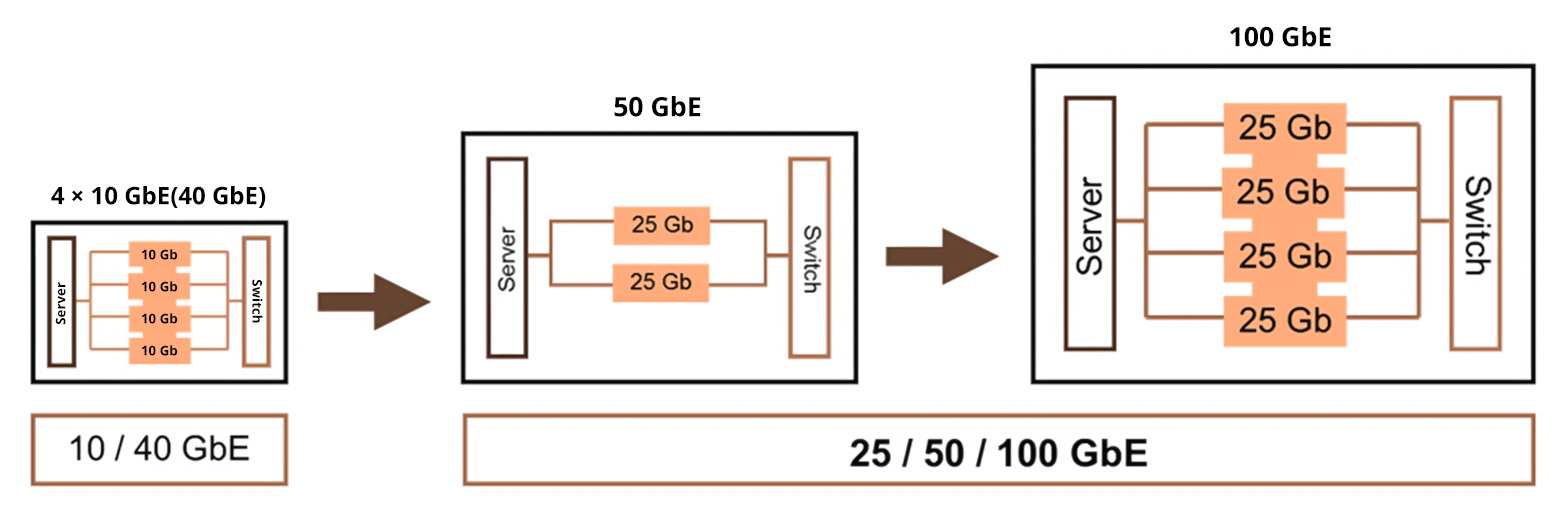
Practically, a dual rate module typically adopts a form factor like SFP28 (small form-factor pluggable 28), commonly utilized in 25Gbps networking but also compatible with 10Gbps, ensuring backward compatibility with older equipment. This empowers IT managers to future-proof their networks and facilitates an upgrade path from 10G Ethernet to 25G Ethernet without necessitating a complete overhaul of the existing cabling infrastructure.
The dual rate functionality proves particularly advantageous for data centres striving to optimize bandwidth, manage costs efficiently, and prepare for escalating data traffic demands, all while maintaining compatibility with existing 10G network equipment.

Applications of Dual Rate 10/25G Transceiver Module
The dual rate 10/25G transceiver module is an optical transceiver that can operate at two different data rates, 10 Gbps and 25 Gbps. This versatility allows the module to be used with a wide range of networking equipment and in various scenarios to meet the demands of modern data centres and enterprise networks. Here are some applications where a dual rate 10/25G transceiver module may be particularly beneficial:
Transitioning to 25G Network via Dual Rate 10/25G Transceiver Module
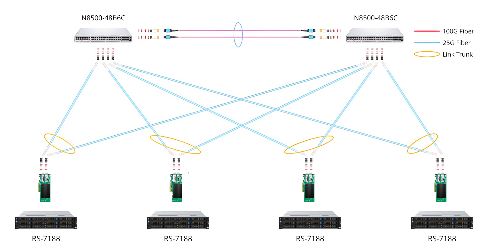
Businesses transitioning from 10G to 25G networks can employ dual rate modules to ensure seamless compatibility throughout the process, facilitating a gradual migration and minimising downtime. Data centres requiring high-bandwidth connections between servers, storage systems, and network switches can benefit from the increased data rates of 25G, while dual rate capability ensures compatibility with existing 10G equipment.
Optimising High-Density Networks
In high-density network environments where rack space is limited, dual rate modules can optimise port density and reduce space requirements by allowing connection consolidation and gradual speed upgrades. Enterprises needing a mix of 10G for legacy devices and 25G for newer, high-throughput applications can utilise dual rate 10/25G transceiver modules for flexible connectivity options.
Enhancing Hybrid Cloud Environments
Organisations operating within hybrid cloud environments can employ dual rate transceivers to facilitate efficient data transfer between different network segments operating at varying speeds. This flexibility enables seamless integration between on-premises and cloud infrastructures.
Versatile Solutions for Telecom Networks
Telecom operators and service providers can leverage dual rate modules to offer customers a range of services operating at either 10G or 25G, providing adaptable solutions tailored to diverse requirements and network demands.
Essentially, dual rate 10/25G transceiver modules assist in offering flexibility, scalability, and investment protection for network infrastructure. They enable network managers to balance performance requirements with budget constraints, and they can be a strategic option for phased network upgrades, ensuring compatibility between different generations of networking equipment.
Introducing FS Dual Rate 10/25G Transceiver Module
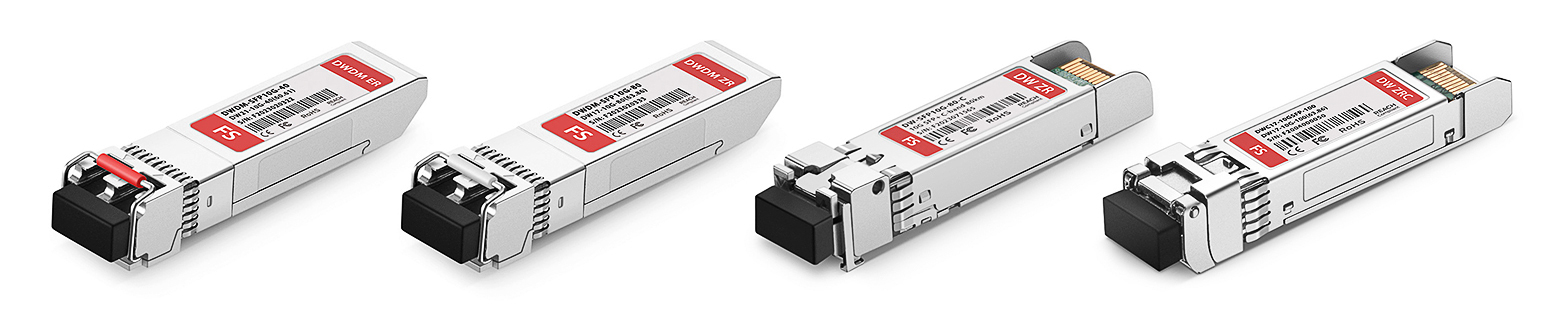
FS dual rate modules have earned high acclaim in the market owing to their outstanding reliability, excellent compatibility, and effective cost management. These modules are distinguished as the preferred option for enhancing network performance and efficiency. Below is a parameter comparison of FS dual rate 10/25G transceiver module FS 10/25G dual rate module.
Conclusion
With the continuous evolution of network technology and the growing demand for flexibility in data centres, dual rate 10/25G transceiver modules are poised with immense potential. Offering a cost-effective solution, they address the challenges of rate adaptability and future compatibility, making them a wise choice for constructing advanced and dependable network infrastructure.
Related Articles:
SFP-10G-SR vs SFP-10G-LRM vs SFP-10G-LR, Which to Choose?
Is SFP Compatible With SFP+? Can 10G SFP+ Run at 1G SFP Gigabit Switch Port?