Intel Network Adapters for Dell PowerEdge R710 Servers

With the growing prevalence of Dell PowerEdge Servers, Dell PowerEdge R710 servers gradually caught Ethernet users’ eyes for its competitive price, superb quality and low power consumption. As one part of the Dell PowerEdge Select Network, Intel Ethernet Network Adapters are high performance adapters for 1/10/25/40GbE Ethernet network connections. This article would give a brief introduction to Dell R710 server, Intel NDC for Dell R710 and optics for Intel NDC.

About Dell R710 Server

The Dell PowerEdge R710 is a 2U rack server that can support up to two quad- or six-core Intel Xeon 5500 and 5600 series processors and to eight SATA or SAS hard drives, giving you up to 18TB of internal storage. It has 18 memory slots allow for a maximum of 288GB of memory, allowing the R710 to support and memory-intensive task you can throw at it. It has low power consumption and high performance capacity, which helps you save both money and time. We would provide detailed information about Dell PowerEdge R710 in the next two parts.

Dell R710 Server

Figure1: Dell R710 2U Rack Server(Resource: www.DELL.com)

Dell R710 Dimensions

Dell R710 Dimensions

Main Features:
—Processors

Dell R710 server adapted Intel’s E5-2600 processors, which have up to 20MB cache and up to 8 cores versus the 5500 and 5600 processors which max out at 12MB Cache and 6 cores. These 8-core processors are ideal for increased security, I/O innovation and network capabilities, and overall performance.

—Storage

The R710 supports a high level of internal storage maxing out at 18TB. That includes up to six 3.5″ hard drives or eight 2.5” hard drives. It provides support for 6Gb/s SAS, SATA, and SSD drives.

—Controller

The R710 sports Dell’s new iDRAC6 management controller, which has a dedicated network port at the rear of the server. It provides a web browser interface for remote monitoring and viewing the status of critical server components, and the Enterprise upgrade key brings in virtual boot media and KVM-over-IP remote access.

—Remote Management

Based on Symantec’s Altiris Notification Server, the Management Console takes over from Dell’s elderly IT Assistant and provides the tools to manage all your IT equipment, instead of just Dell servers. Installation is a lengthy process, but it kicks off with an automated search process that populates its database with discovered systems and SNMP-enabled devices.

Intel network Adapters for Dell PowerEdge R710 servers

According to Dell PowerEdge R710 datasheet, the Dell PowerEdge R710 servers support dual port 10GB enhanced Intel Ethernet server adapter X520-DA2. This Dell Intel Ethernet Network Daughter Card X520/I350 provides low cost, low power flexibility and scalability for the entire data center. The Intel Ethernet Network Daughter Card X520-DA2/1350-T2 provides two 1000BA

SE-T ports and two 10G SFP+ ports as shown in Figure 2 to support 1GbE/10GbE Ethernet network connectivity.

Intel Ethernet Network Daughter Card X520-DA2

Figure2: Intel Ethernet Network Daughter Card X520-DA2

Cables And Optical Modules for Intel NDC X520-DA2

As we mentioned before, the Intel Ethernet Network Daughter Card X520-DA2 provides two 1000BASE-T ports and two 10G SFP+ ports respectively. We can plug two Intel compatible SFP transceivers into the two 1G ports on the Intel NDC X520-DA2 respectively to achieve 1G network connection. Likewise, we can also connect Intel compatible SFP+ transceiver to the 10G port on the Intel card for making 10G data transferring. In addition, we can also use Direct Attach Cable (DAC) to achieve 10G network connectivity, such as 10Gb fiber optic cable, Intel 10G SFP+ DAC cable. DAC cables are suitable for data transmission over very short link length while optical modules are more appropriate for longer transmission distance.

Intel NDC X520-DA2 with 10G optical modules

Figure3: Intel NDC X520-DA2 with 10G optical modules

Conclusion

The Dell R710 server with the high performance of Intel Ethernet Network Daughter Card X520-DA2 offers you a 2U rack to efficiently address a wide range of key business applications. With the great Intel NDC card, it also provides you a perfect solution for 1G and 10G Ethernet network connectivity. You can rest assured to enjoy a low consumption but high capacity server to keep your business.

Related Articles: 
Can We Use Third-party Dell SFP for Dell Switches?
Dell Powerconnect 2700 Vs. 2800 Series Switches

Cisco Nexus 7010 Vs. Nexus 7710

We know that fiber optic cable and transceiver are important components to complete the whole optical link. In addition, there is another core component in data center—switch, which is the nerve center of the whole network deployment. This article will introduce two Cisco switches—Cisco Nexus 7010 switch and Cisco Nexus 7710 switch, and make a comparison between the two network switches.

Overview of Cisco Nexus 7010 Switch And Cisco Nexus 7710 Switch

Characterized by high availability and scalability, comprehensive Cisco NX-OS Software data center switching feature set, Cisco Nexus 7010 switch and Nexus 7710 switch is designed to satisfy the demand for high switching capacity in data centers. As Cisco Nexus 7700 Series switches are the latest extension to the Cisco Nexus 7000 Series switches, there are similarities and differences between 7010 and 7710 switch. How much do you know about them? Keep reading and you will find the answer. The following figures show Cisco 7010 and 7710 switch.

Cisco Nexus 7010

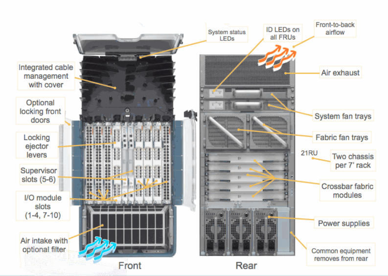
Figure 1. Cisco Nexus 7010 switch

Cisco Nexus 7710

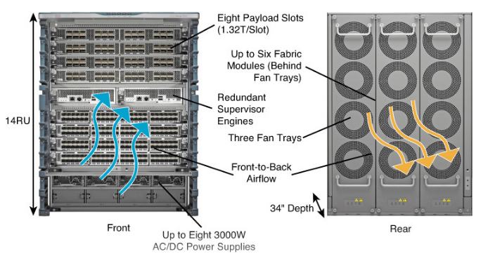
Figure 2. Cisco Nexus 7710 switch

Cisco Nexus 7010 Vs. Nexus 7710

From the above figures, we can have a basic knowledge of the two network switches. And the following part will focus on the similarities and differences between them.

Similarities Between Cisco Nexus 7010 Switch And Cisco Nexus 7710 Switch
  • Both of them are 10-slot chassis switch with 2 dedicated supervisor modules and 8 I/O modules.
  • Both of them are structured with 384 x 1 and 10 Gigabit Ethernet ports.
  • Both of them utilize front-to-back airflow which can ensure that switch addresses the requirement for hot-aisle and cold-aisle deployments to help provide efficient cooling.
  • Both of their I/O modules and supervisor modules are accessible from the front, and fabric modules and fan trays are accessible from the back of the chassis.
  • Both of their fan trays are composed of independent variable-speed fans which can automatically adjust to the ambient temperature, and this helps reduce power consumption in well-managed facilities while enables optimum operation of the switch.
  • Both of their systems not only allow hot swapping without affecting the system, but also support air filter to promote clean airflow through the system.
Differences Between Cisco Nexus 7010 Switch And Cisco Nexus 7710 Switch
  • Cisco Nexus 7010 switch has 48 x 40 Gigabit Ethernet ports, and 16 x 100 Gigabit Ethernet ports. While Cisco Nexus 7710 switch has 192 x 40 Gigabit Ethernet ports, and 96 x 100 Gigabit Ethernet ports.
  • Cisco Nexus 7010 switch has 5 fabric module slots and 3 power supply slots. While Cisco Nexus 7710 switch has 6 fabric module slots and 8 power supply slots.
  • Cisco Nexus 7010 switch supports Fabric—1 and Fabric—2 modules while Cisco Nexus 7710 switch supports only Fabric—2 modules.
  • Cisco Nexus 7010 switch is designed with 21RU height, bigger than Cisco Nexus 7710 switch’s 14RU height.
  • Cisco Nexus 7010 switch uses dual system and fabric fan trays for cooling. While Cisco Nexus 7710 switch uses three redundant fan trays for cooling.
  • The maximum inter-slot switching capacity with the Cisco Nexus 7010 switch is 550 Gbps while Cisco Nexus 7710 switch can achieve the maximum inter-slot switching capacity of 1.2 Tbps.
  • Cisco Nexus 7010 switch supports F1, F2 and F2e line cards while Cisco Nexus 7710 switch supports F2e and F3 line cards.
  • Cisco Nexus 7010 switch supports SUP1, SUP2 and SUP2E supervisors while Cisco Nexus 7710 switch supports only SUP2E supervisor engines.
  • Cisco N7K-C7010-FAN-Sis US $1,100.00 on eBay while Cisco N77-C7710-FAN is US $1,299.99.

Which One to Choose?

Both the two network switches are designed to meet the scalability requirements of the largest cloud environments. As for which one to choose, it all depends on your individual requirements. If you need higher switching capacity and smaller size, you can choose Cisco Nexus 7710 switch; if your budget is tight, Cisco Nexus 7010 switch is a good option; if you want your switch to support F1 line card and SUP1 supervisor engineer, you have to buy Cisco Nexus 7010 switch. FS.COM provides large stock single mode fiber patch cables and multimode fiber patch cables. Also, you can find various types of Cisco compatible transceiver modules for your Cisco network switch. For more details, please visit our site.

Related Articles: 

Enterprise Network Switch Deployment Case Study and FAQ

Data Center Switch Wiki, Usage and Buying Tips

Network Virtualization and Challenges in SDN/NFV Implementation

Software defined networking (SDN) and network functions virtualization (NFV) are two closely related technologies that are both toward network virtualization and automation. The occurrence of these two technologies are mainly driven by the requirements for robust data management systems and access to bandwidth by servers located at different sites and connected over long distances through public and private clouds. SDN and NFV have some similarities but they are different in many aspects. In addition, though SDN and NFV are highly promoted as next-generation dominants in recent years, there are still many challenges in successfully deploying them. This post will give some basic knowledge of SDN vs NFV, and the challenges faced in implementing SDN and NFV.

SDN vs NFV: What Are They?

Although SDN and NFV are both network virtualization technologies, they’re really not dependent on each other. And it is not always necessary to involve them in the same network. The infrastructures of SDN and NFV will be explained in the following text, and the major differences between them will be displayed.

What Is SDN?

The function of SDN is somewhat hinted by its name. With SDN, the users are able to manage and control the entire network through software that makes networks centrally programmable. It achieves this by separating the system that decides where traffic is sent (the control plane) from the underlying system that pushes packets of data to specific destinations (the data plane). As known to network administrators and value added resellers (VARs), SDN is built on network switches that can be programmed through an SDN controller based on an industry standard controller like OpenFlow.

What Is NFV?

Network function virtualization is similar to traditional server virtualization mechanisms but clearly focuses on networking services. Within NFV, they’re virtualized network functions. It means NFV separates network functions from routers, firewalls, load balancers and other dedicated hardware devices and allows network services to be hosted on virtual machines. Virtual machines have a manager, which allows multiple operating systems to share a single hardware processor.

SDN vs NFV: What Are the Differences?

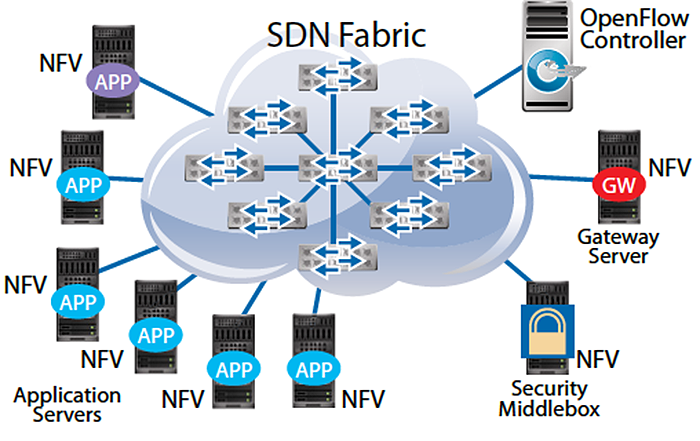
Both SDN and NFV rely on software that operates on commodity servers and switches, but both technologies operate at different levels of the network. They are not dependent and you could perfectly have just an NFV platform operating a piece of your environment without the inclusion of full-developed SDN or only SDN. The following figure shows a use case of SDN and NFV.

SDN vs NFV

The differences between SDN vs NFV can be summarized from five aspects. They are presented in the table below.

SDN NFV
Basics SDN separates control and data and centralizes control and programmability of the network. NFV transfers network functions from dedicated appliances to generic servers.
Areas of Operation SDN operates in a campus, data center and/or cloud environment. NFV targets the service provider network.
Initial Application Target SDN software targets cloud orchestration and networking. NFV software targets routers, firewalls, gateways, WAN (wide area network), CDN (content delivery network), accelerators and SLA (service level agreement) assurance.
Protocols OpenFlow. No protocols, yet.
Supporting Organization Open Networking Foundation (ONF). ETSI NFV working group.


Challenges in SDN/NFV Implementation

Though SDN and NFV are promising technologies, there are still many roadblocks in their deployments. Complete standards and proven examples are still needed for wider implementation of SDN/NFV.

Security is one of the biggest concerns in implementing SDN. While centralized control and virtualization of network topology are powerful assets that SDN allows, they also create new security vulnerabilities that must be addressed. The positive side of implementing SDN is that the user is able to make uniform security policies across the whole system. But naturally, the negative side is that, if the SDN controller is successfully hacked, the attacker would have complete control of the system.

Another major challenge is the scalability of SDN systems, in the view of the virtualization that comes with the SDN systems (via NFV). It is a fact that the continuous growth of network data consumption makes scalability a challenge for any network system. If integrated properly, SDN can improve the scalability in a given data center or network. But there are scalability concerns raised by the SDN architecture. Since it is a single item, the centralized SDN controller is not necessarily scalable for larger networks. This also presents a single point of failure in the network, which would be dangerous if the controller or an uplink device fails. There are potential solutions to this problem, but these are still in development.

As for NFV implementation, there are challenges for NFV independent software vendors (ISVs). The first challenge is to develop an innovative, virtualized product that meets the reliability and scalability requirements of the telecom industry. In addition to technical challenges, ISVs also have to develop a concise value proposition to convince the large telcos why they should adopt a new, unproven product into their highly complex network operations.

Conclusion

To sum up, when SDN vs NFV, it is no doubt that both of them can bring many benefits to network administrators by accomplishing virtualization and automation of the systems. And it also cannot be denied that there are still many improvements needed to be made for SDN and NFV deployments. Knowing the pros and cons of them can help in correctly facing these technologies and avoid blind following up or complete refusal to new products. FS.COM has announced new 10/40/100GbE open networking switches for data centers and enterprise networks, which support SDN/NFV. Also high performance 40G and 100G DAC and optical transceivers are provided at competitive prices. For more details about SDN switches, please visit www.fs.com or e-mail to sales@fs.com.

Related Articles:
SDN and NFV: What Is the Difference?
What White Box Switch Means to SDN Deployment

Things We Should Know Before Migrating to Base-8 System

Since the introduction of Base-12 connectivity in the mid 1990s, the 12-fiber MTP/MPO connector and Base-12 connectivity have served the data center for about twenty years. It has helped a lot in achieving high-density and manageable cabling. Recently, many documents and posts are discussing about a new technology—Base-8. Its appearance is regarded as the evident need of future networks. Even though most of the words are promoting the overwhelming advantages of Base-8 system, we should still consider the defects and merits of these two systems based on some facts before taking the next step by ourselves. This post is a discussion on this topic.

Facts of Base-12 and Base-8

In this part, the design features of Base-12 and Base-8 systems will be introduced. And their dominant advantages are going to be discussed too.

Design Features

Base-12 connectivity makes use of links based on groups of 12, with 12-fiber connectors such as the MTP. In Base-12 connectivity, for example, trunk cables have fiber counts that are divisible by number 12, like 24-fiber trunk cable, 48-fiber trunk cable and all the way up to 144 fibers. However, in a Base-8 system, we don’t have 12-fiber trunk cable, instead we have 8-fiber trunk cable, 16-fiber trunk cable, 32-fiber trunk cable and so on. All trunk cables are based on increments of 8 fibers.

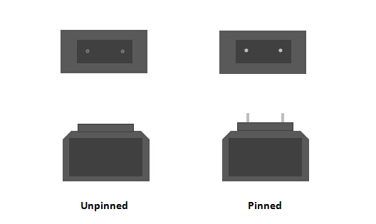
Base-12 and Base-8 trunk cables are visually different on connector design. A Base-12 trunk cable generally has unpinned (female) connectors on both ends and demands the use of pinned breakout modules. In the new emerging Base-8 system, a trunk cable is designed with pinned (male) connectors, as a result, it should be connected to unpinned components.

pinned & unpinned connectors
Figure: Unpinned Connector and Pinned Connector
Comparison

Compared with Base-8, Base-12 obviously has the benefit of higher connector fiber density. Thus a larger number of fibers can be installed more quickly when using Base-12 connectivity. And it is very easy to be deployed into all-ready existing Base-12 architecture. As the networks are migrating to 40G and 100G data speeds, Base-8 connectivity has some advantages that cannot be denied. For some 40G and 100G applications, including SR4 (40G and 100G over parallel MMF) and PSM4 (100G over parallel SMF) supported eight-fiber transceivers, and SAN switch Base-8/Base-16 port arrangements, Base-8 connectivity is a more cost-effective choice. In these applications, Base-8 enables full fiber utilization for eight-fiber transceiver systems. But Base-8 connectivity is not optimized for all situations, including duplex protocols like 25G and 100G (duplex SMF).

Correct Co-existence of Base-8 and Base-12

If we are going to deploy Base-8 devices in our existing network, it is possible to have Base-12 and Base-8 connectivity at the same time as long as we do not mix them in the same link. On one hand, it is not wise to use conversion module between Base-12 and Base-8 devices, because the added cost and increased insertion loss will surpass the benefits it can brought. As mentioned before, the two systems are not interchangeable since they usually have different connector configurations and have unequal attachment requirements. Therefore, special care should be given when managing the data canter physical layer infrastructure, to ensure that the Base-12 and Base-8 components are used separately.

Conclusion

When a new technology comes out as a new option for us, we need to decide whether to change or not. In terms of the discussion on Base-12 and Base-8 systems, after listening to voices from different sides, the key factors are still determined by own specific needs. If we decided to move to the new technology, the following question is how to realize the best migration. Having comprehensive understanding of the solutions and products vendors supply will never be a bad choice.

MTP-8: Simplest Way to Get 40G Connection

As data centers networks are shifting from 10G to 40G and beyond, it is necessary to seek ideal ways to connect 40G high speed switches populated with higher rate transceivers QSFP+, and to connect 40G switch to existing 10G elements populated with SFP+ modules. There are different approaches to connect 40G switches, or to connect 40G switch to 10G switch. However, by using MTP-8 solution, the simplest way to achieve direct 40G connectivity has been proved feasible and favorable in real applications. This article will introduce the deployment of MTP trunk cable in 40G to 40G connection, and MTP harness cable in 10G to 40G connection.

Basis of MTP Trunk and Harness Cable

MTP trunk cable has MTP connectors terminated on both ends of the fiber optic cable. It is often used to connect MTP port modules for high density backbone cabling in data centers and other high dense degree environments. Currently, most of the MTP trunk cables for high data rate like 40G and 100G are still 12-fiber or 24-fiber. MTP harness cable, also called MTP breakout or fan-out cable, has MTP connectors on one end and discrete connectors (duplex LC, SC, etc.) on the other end. The most common configurations of MTP-LC harness cables are 8-fiber MTP to 4 LC duplex, 12-fiber MTP to 6 LC duplex and 24-fiber MTP to 12 LC duplex. A single MTP connector is able to terminate the combination of 4, 8, 12, 24, 48 fiber ribbon cables. The multi-fiber design provides quick deployment and scalable solution that improves reliability and reduces installation or reconfiguration time and cost.

10G to 40G Connection via MTP Harness Cable

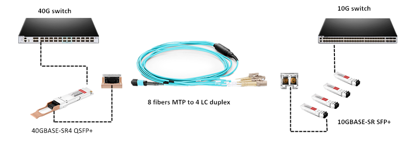
In order easily and quickly finish the migration from 10G network to 40G network, you can use 8-fiber MTP to 4 LC duplex harness cable, 40GBASE-SR4 QSFP+ and 10GBASE-SR SFP+ modules. The configuration of such a link is illustrated by figure 1. On the left the 8-fiber MTP connector is plugged into the MTP port of the 40GBASE-SR4 QSFP+ transceiver installed on the 40G switch; on the right side four duplex LC connectors are plugged into the ports of four 10GBASE-SR SFP+ transceivers installed on the 10G switch. In 10G to 40G migration, using 8-fiber MTP to LC harness cable can ensure every strand of fiber be used, and no one wasted.

10G to 40G via MTP-8 harness

Figure 1: 10G to 40G Migration via MTP-LC Harness Cable

40G to 40G Connection via MTP Trunk Cable

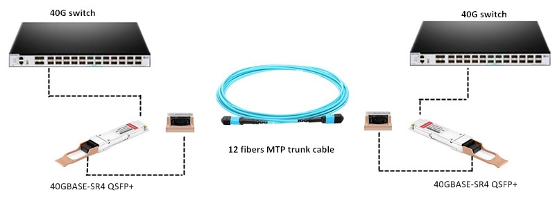
To support your 40G networking needs, you can simply use 12-fiber MTP trunk cable and 40GBASE-SR4 QSFP+ transceiver to accomplish a quick connection for two 40G switches in your network. The following figure shows a concrete example which uses one 12-fiber MTP trunk cable and two 40GBASE-SR4 QSFP+ transceivers to connect two 40G switches. Though the MTP trunk cable in this case is base-12, the fiber count actually in use is eight, leaving four strands unused. That is to say delivering 40G over 4 lanes multimode fiber at 10 Gb/s per lane. Totally only eight fibers (4 transmit, 4 receive) are required for the 4x10G solution. It is the same as the 4x25G solution for 100G.

40G connection via MTP-8 trunk

Figure 2: 40G to 40G Connection via MTP Trunk Cable

The above two examples are both applications of MTP-8 solution in 40G connectivity. You will find that only a few components are needed in the whole installation, and the link will be very easy and flexible, as well as cost-effective.

Conclusion

Current 40G connectivity can be obtained by MTP-8 solution. Though present market is still popular with 12-fiber or 24-fiber MTP, 8-fiber MTP solutions that are starting to hit the market are considered the most efficient option since they support current and future duplex fiber applications (such as 200G and 400G) and using modules that break out 8-fiber MTPs to duplex LCs, as well as current and future 8-fiber applications without the need for conversion cords or modules.