Data Center Architecture Designs Comparison: ToR Vs. EoR

The interconnection of switches and warranty of data communication are the basic aspects to consider when designing a data center architecture. Today’s data centers have been shifted into 1RU and 2RU appliances, thus setting the 1RU and 2RU switches into the same-sized racks can greatly save space and reduce cabling demands. Typically, Top of Rack (ToR) and End of Row (EoR) are now the common infrastructure designs for data centers. In this article, we will mainly discuss the differences between these two approaches.

tor-eor

Overview of ToR & EoR
What Is ToR?

ToR approach refers to the physical placement of network access switch in the top of a server rack. Servers are directly linked to the access switch in this method. Each server rack usually has one or two access switches. Then all the access switches are connected with the aggregation switch located in the rack. Only a small amount of cables are needed to run from server rack to aggregation rack.

top-of-rack

What Is EoR?

In the EoR architecture, each server in individual racks are directly linked to a aggregation switch eliminating the use of individual switches in each rack. It reduces the number of network devices and improves the port utilization of the network. However, a large amount of cables is needed for the horizontal cabling. Along with the EoR approach, there is also a variant model named as MoR (Middle of Row). The major differences are that the switches are placed in the middle of the row and cable length is reduced.

end-of-row

Comparison Between ToR & EoR
Benefits

As for ToR, the cost of cables are reduced since all server connections are terminated to its own rack and less cables are installed between the server and network racks. Cable management is also easier with less cables involved. Technicians can also add or remove cables in a simpler way.

In the EoR, device count is decreased because not every rack should equip the switches. Thus, less rack space is required in the architecture. With less devices in data center, there will be less requirements for the cooling system which also reduces the using of electricity power.

Limitations

In reverse, there are also some limitations for each architecture. For ToR, although the cables are reduced, the number of racks is still increased. The management of switches may be a little tricky. In addition, ToR approach takes up more rack space for the installation of switches.

As for EoR, its Layer 2 traffic efficiency is lower than the ToR. Because when two servers in the same rack and VLAN (virtual local area network) need to talk to each other, the traffic will go to the aggregation switch first before comes back. As less switches are used in EoR design, more cables are deployed between racks triggering higher possibility of cable mess. Skillful technicians are required when carrying out the cable management.

Physical Deployments of ToR & EoR
ToR Deployment

One is the redundant access switch deployment which usually demands two high-speed and individual ToR switches that connect to the core network. Servers are interconnected to access switches deployed within the server racks. Another is the server link aggregation with ToR deployment. Two high-speed ToR switches are part of the same virtual chassis. Servers can connect to both of the switches located at top of rack with link aggregation technology.

EoR Deployment

EoR access switch deployment is very common to extend all the connections from servers to the switching rack at the end of row. If the deployment is needed to support the existing wiring, you can also deploy a virtual chassis.

Conclusion

ToR and EoR are the common designs for data center architecture. Choosing the proper one for your network can promote the data center efficiency. From this article, you may have a general understanding about these two methods. Hope you can build up your data center into a desired architecture.

Related Article: How to Choose Optical Distribution Frame?

Popular ToR and ToR Switch in Data Center Architectures

Key Components to Form a Structured Cabling System

Building a structured cabling system is instrumental to the high performance of different cable deployments. Typically, a structured cabling system contains the cabling and connectivity products that integrates the voice, data, video, and various management systems (e.g. security alarms, security access, energy system, etc.) of a building. The structured cabling system is based on two standards. One is the ANSI/TIA-568-C.0 of generic telecommunications cabling for customer premises, and another is the ANSI/TIA-568-C.1 of commercial building telecommunications cabling for business infrastructures. These standards define how to design, build, and manage a cabling system that is structured. Six key components are included to form a structured cabling system.

Six Subsystems of a Structured Cabling System

Generally speaking, there are six subsystems of a structured cabling system. Here will introduce them respectively for better understanding.

structured-cabling-system

Horizontal Cabling

The horizontal cabling is all the cabling between telecommunications outlet in a work area and the horizontal cross-connect in the telecommunications closet, including horizontal cable, mechanical terminations, jumpers and patch cords located in the telecommunications room or telecommunications enclosure, multiuser telecommunications outlet assemblies and consolidation points. This type of wiring runs horizontally above ceilings or below floors in a building. In spite of the cable types, the maximum distance allowed between devices is 90 meters. Extra 6 meters is allowed for patch cables at the telecommunication closet and in the work area, but the combined length of these patch cables cannot exceed 10 meters.

Backbone Cabling

Backbone cabling is also known as vertical cabling. It offers the connectivity between telecommunication rooms, equipment rooms, access provider spaces and entrance facilities. The cable runs on the same floor, from floor to floor, and even between buildings. Cable distance depends on the cable type and the connected facilities, but twisted pair cable is limited to 90 meters.

Work Area

Work area refers to space where cable components are used between communication outlets and end-user telecommunications equipment. The cable components often include station equipment (telephones, computers, etc.), patch cables and communication outlets.

Telecommunications Closet (Room & Enclosure)

Telecommunications closet is an enclosed area like a room or a cabinet to house telecommunications equipment, distribution frames, cable terminations and cross connects. Each building should have at least one wiring closet and the size of closet depends on the size of service area.

Equipment Room

Equipment room is the centralized place to house equipment inside building telecommunications systems (servers, switches, etc.) and mechanical terminations of the telecommunications wiring system. Unlike the telecommunications closet, equipment room houses more complex components.

Entrance Facility

Entrance facility encompasses the cables, network demarcation point, connecting hardware, protection devices and other equipment that connect to the access provider or private network cabling. Connections are between outside plant and inside building cabling.

Benefits of Structured Cabling System

Why do you need the structured cabling system? Obviously, there are many benefits for using the system. A structured cabling can standardize your cabling systems with consistency so that the future cabling updates and troubleshooting will be easier to handle. In this way, you are able to avoid reworking the cabling when upgrading to another vendor or model, which prolongs the lifespan of your equipment. All the equipment moves, adds and changes can be simplified with the help of structured cabling. It is a great support for future applications.

structured-cabling

Conclusion

From this article, we can know that a structured cabling system consists of six important components. They are horizontal cabling, backbone cabling, work area, telecommunications closet, equipment room and entrance facility. Once you split the whole system into small categories, the cabling target will be easier to get. As long as you keep good management of these subsystems, your cabling system is a success to be called as structured wiring.

Importance of Using Fiber Color Codes in Data Center

The utilization of fiber color code in data center effectively helps technicians make better cable management and reduce human errors. Without redundant checking process, people can easily get the information of the device by only one look. Making good use of the color code system can surely save much time during work. This article will mainly present the widely accepted color code system and its important functions.

fiber color code

Introduction to Fiber Color Code Systems

Fibers, tubes and ribbons in fiber optic cables are usually marked with different color codes to facilitate identification. There are many color code systems for national or international use. All these systems are characterized by using 12 different colors to identify fibers that are grouped together in a common bundle such as a tube, ribbon, yarn wrapped bundle or other types of bundle.

Different color code standards may be used in different regions. For example, the S12 standard is used for micro cables and nano cables in Sweden and other countries. The Type E standard is defined by Televerket and Ericsson used in Sweden. The FIN2012 standard is used in Finland, etc. However, there is one color code system widely recognized in the world, namely the TIA/EIA-598 standard.

Specifications of TIA/EIA-598 Color Codes

The following picture gives the fiber color coding of TIA/EIA-598 standard. If more than 12 fibers or tubes are to be separated, the color sequence is normally repeated with ring marks or lines on the colored fibers and tubes. As for the fiber cable jacket, orange, yellow, aqua and black color codes are used for their distinction.

color-code-system

Functions of Fiber Color Code in Data Center
Distinguishing Fiber Grades

As mentioned above, the outer jacket color codes are able to identify the fiber grades. OM1/OM2 cables often adopt the orange jacket, OM3/OM4 cables with aqua jacket, single-mode cables with yellow jacket and hybrid cables (indoor/outdoor cables and outside plant cables) with black jacket. One thing to note is that the mix of OM1 and OM2 or OM3 and OM4 cables may be troublesome. You should make sure not to mingle these cables with the same color code.

Identifying Fiber Patch Cords

Using fiber color code to label fiber patch cords can reduce the potential for human error. For instance, you may highlight mission-critical patch cords in red, and then teach all technicians that a red patch cord should only be moved with proper authorization or under supervision. Likewise, keeping the fiber connector color consistent with fiber grade color standards will make it simple for technicians to use the right connectors with the cables.

Separating Different Ports

The color-coded port icons can be helpful in identifying different network routings in accordance with internal needs. By tagging each patch panel port, you can simplify and streamline network management.

Differentiating Connector Boots

You can use fiber color code on connector boots to make routine maintenance and moves, adds and changes easier by helping technicians preserve correct parallel groupings for switch ports. If you change your connector color, you need to ensure that your fiber cable color represents the fiber grade to avoid confusion. You can also change the color of a connector boot to differentiate between different aspects of the network, making it easy for technicians to view the contrast within a panel.

Conclusion

Visual management is more intuitive for specialists to supervise the data center. Color code system has provided an ideal and easy way to solve the cabling problem. Inside the cables, the fiber buffers are also color-coded with standard colors to make connections and splices easier. Therefore, if you are still bothered by these issues of fiber patch cables, using the fiber color code system is a good way to go.

Related Articles:
How to Identify the Color Codes?
Fiber Patch Panel Color Codes

How to Choose Optical Distribution Frame

Due to the development of high speed transmission, demands for high density patching have increased in recent years. However, the management of installed cables still remains a difficult task. To achieve a simpler way of cable organization, people often use the cost-effective optical distribution frame (ODF) to arrange optical cable connections. ODF plays an important part in building a safe and flexible operating environment for the optical network. Different kinds of ODFs are provided in the market, but you need to choose the right one according to the actual situation.

Functions of Optical Distribution Frame

ODF is mainly used for fiber optic terminal splicing, fiber optic connector installation, optical path adjusting, excess pigtail storage and fiber optic cable protection. When cable enters into the rack, ODF should mechanically fix the cable and install the ground wire protection. Fiber optic cables will also be divided into groups for better management. When it comes to the spliced fibers, extra parts will be stored as a coil and the fusion splices are well-protected in the ODF. Adapters and connectors are pluggable and optical path can be freely adjusted or tested. Moreover, enough space of ODF is provided to satisfy a clear connection.

Things to Consider for Choosing ODF

Selecting a right ODF is vital to future applications. Here are some recommended aspects for you to consider before purchasing:

1) ODF Types

Generally, there are three types in terms of its structure. They are wall mount ODF, floor mount ODF and rack mount ODF. Wall mount ODF shapes are like a small box installed on the wall. Because space is restrained, wall mount ODF only accepts small fiber counts. Floor mount ODF has a fixed and large fiber capacity in a closed structure. Rack mount ODF is more flexible to be installed on the rack to meet your requirements for different cable counts and specifications. This type is frequently used in the optical distribution system with 19 inches’ specification to accommodate the size of standard transmission rack.

rack-mount-optical distribution frame

2) Fiber Counts

High density fiber counts have become the trend for future data center. Today, a single ODF unit usually has 12, 24, 36, 48, 72, 96 or even 144 ports. Customized ODF according to your needs is also available in the market.

3) Easy Management

Using a high density device will definitely increase the difficulty of cable management. ODF should allow for easy access to the connectors on the front and rear ports for quick insertion and removal, which means that ODF must provide adequate space. Besides, ODF should have the right colored adapters to match with optical connectors in case of wrong connections.

4) Good Protection

One basic function of ODF is the protection function. A standard ODF should comprise protection devices to prevent fiber optic connections from dust or stress damages. For instance, the splicing connection is very sensitive to the outside environment and is important to the normal operation of a network, so the good quality of ODF protection device is of great importance.

Conclusion

In a word, optical distribution frame is now an indispensable equipment for the deployment of optical network. High-density ODF is especially popular in the industry. To find a suitable ODF with a lower price, careful selection is important. This article only provides some basic factors that may affect the application of ODF. For more information, please visit FS.COM.

10GbE or More – The Choice of Virtualization and Cloud Computing

At one time, data centers were discrete entities consisting of independent silos of computing power and storage bridged together by multiple networks. Servers were consolidated from time to time, but they still used discrete and independent networks such as Token Ring, Ethernet, Infiniband*, and Fibre Channel.

Then along came virtualization and cloud computing. They brought with them a variety of storage technologies and, more recently, Software Defined Networking (SDN). Collectively, these technologies are providing dramatic gains in productivity and cost savings. They are also fundamentally changing enterprise computing and driving a complete rethinking of enterprises’ networking architecture strategies.

Cloud Computing

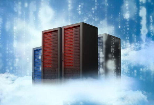
As virtualization continues to take hold in data centers, the silos of computing, network, and storage that were once fixtures are increasingly being replaced by resource pools, which enable on-demand scalable performance. Hence, as application needs grow, the infrastructure can respond.

Unfortunately, this is a two-edged sword. Virtualization has increased server utilization, reducing the once-prevalent server sprawl by enabling enterprises to do more with less, and simplifying and maximizing server resources. But it has also driven the demand for networking bandwidth through the roof in complexity and created a major bottleneck in the system.

For some enterprises, server virtualization alone isn’t enough and they have deployed a private cloud-based infrastructure within their data center. With this comes the need to not only scale resources for a specific application but also for the data center itself to be able to scale to meet dynamic business needs. This step requires storage and networking resources to move away from the restriction of dedicated hardware and be virtualized as well.

This next step in virtualization is the creation of a virtual network that can be controlled and managed independent of the physical underlying compute, network, and storage infrastructure. Network virtualization and SDN will play a key role, and network performance will ultimately determine success.

Today, discrete data center networks for specific components, such as storage and servers, are no longer appropriate. As companies move to private cloud computing, in which systems are consolidated onto fewer devices, networks must be simpler to deploy, provision, and manage.

Hence, 1GbE connectivity is no longer enough. Think about it: Servers are getting faster, and enterprises are running a growing number of Virtual Machines (VMs) that compete for existing I/O on each server. An increased amount of data must be processed, analyzed, shared, stored, and backed up due to increased VM density and enterprises’ rising storage demands. If this growth is left unmanaged, the network will become even more of a bottleneck, even as server speeds continue to increase.

To truly reap these gains, the network needs to keep up. More bandwidth means faster access to storage and backup, and faster network connections mean lower latency and a minimal bottleneck.

Moving to 10GbE

Despite its recent maturity, 10GbE has had a long journey. Initially ratified by the IEEE in June 2002 as 802.3ae, the standard is a supplement to the 802.3 standard that defines Ethernet.

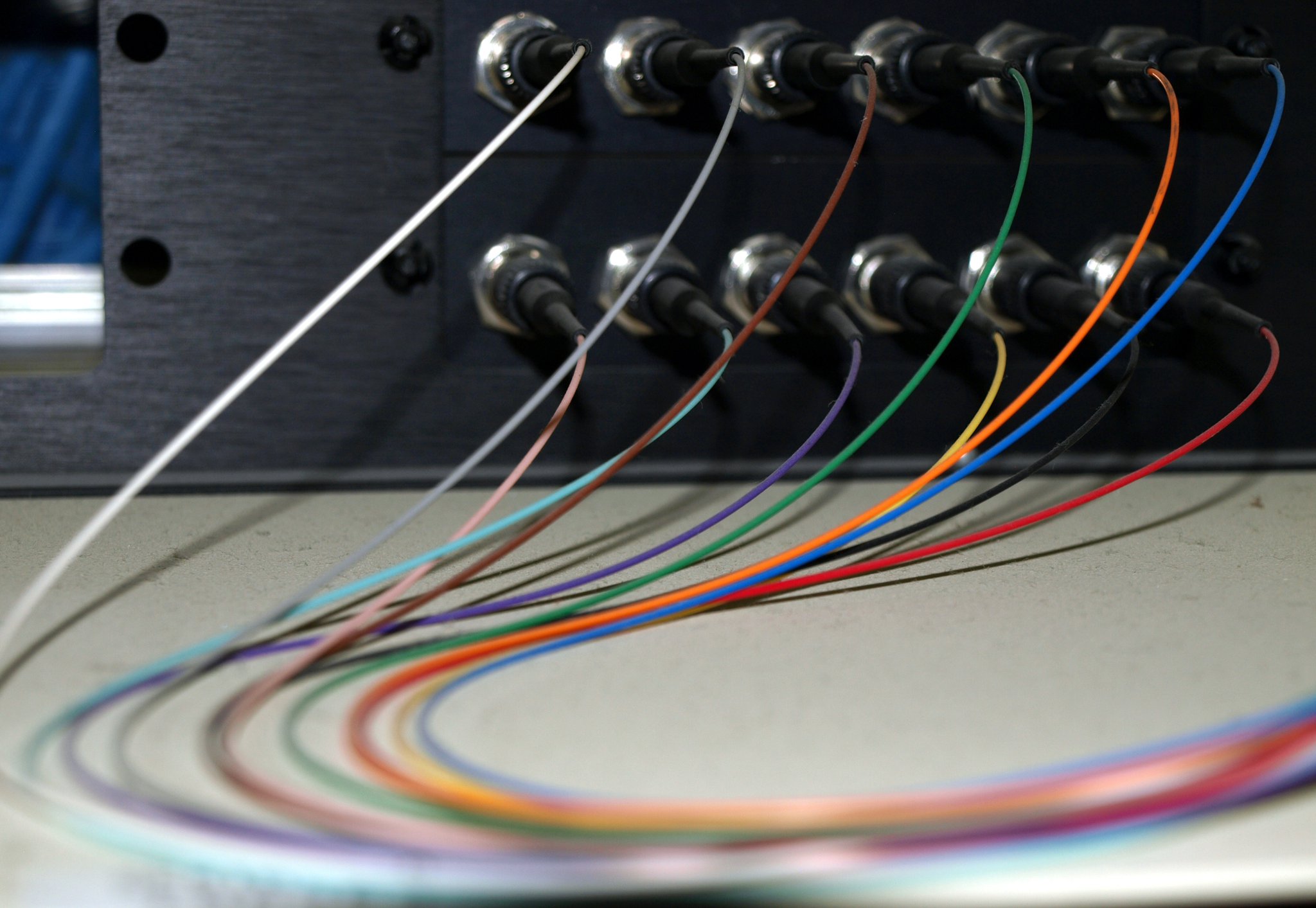
Officially known as 10 Gigabit Ethernet, 10GbE (also referred to as 10G) operates in only full-duplex mode and supports data transfer rates of 10 gigabits per second for distances up to 300 meters on multimode fiber optic cables and up to 10 kilometers on single-mode fiber optic cables.

Although the technology has been around for many years, its adoption has been slow. After spending nearly a decade building out their 1GbE networks, enterprise have been reluctant to overhaul the resources invested in the network, including adapters, controllers and other devices, and—perhaps most of all—cabling. But as virtualization and cloud operations become core technology components, they are bringing with them changing network requirements, key to which is that the minimum for an advanced dynamic architectures is now 10GbE.

Crehan Research reported that while 17 percent of server Ethernet ports conformed to the 10GbE standard in 2012, the majority—83 percent—still followed the 1GbE standard. In 2013, those numbers remained steady, with 81 percent and 19 percent following the 1GbE and 10GbE standards, respectively. 2014, however, was expected to be a year of change. Crehan Research forecasted that 10GbE usage would increase, with 28 percent of server Ethernet ports adhering to the standard. Inversely, 1GbE installs would decline to 72 percent. This trend was expected to continue through 2018, at which time 79 percent of server Ethernet ports would be using 10GbE and a mere 4 percent 1GbE. The remaining ports would have migrated to 40GbE.

For some time now, hardware vendors have been designing their products—from processors to interconnects and switches—with 10GbE in mind. Software vendors are now well-versed in these needs as well and are designing applications that take advantage of 10GbE. Enterprises are now in effect paying for an optimization for which they may not be reaping the benefits. Fortunately, while this ecosystem around 10GbE has been growing and the speed is now expected if an enterprise is to achieve its desired performance, price points of 10GbE supported products have been dropping.

The benefits 10GbE brings to data centers can be classified into three categories: Performance, Simplification, and Unification.

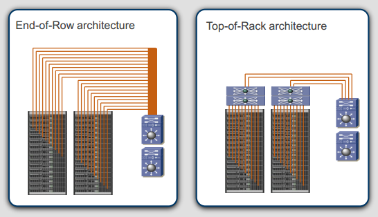
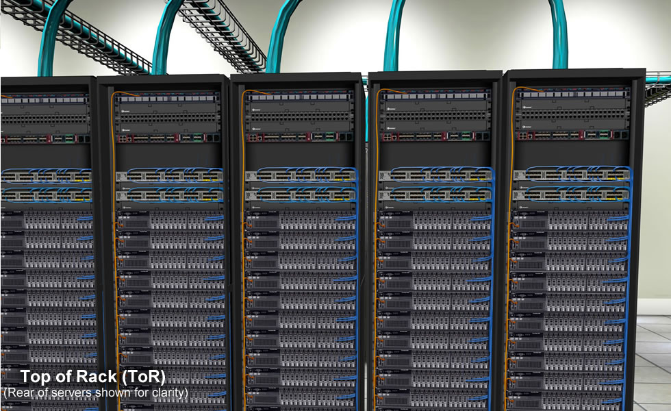
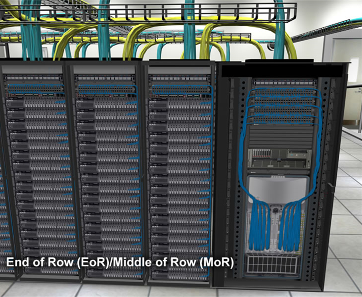
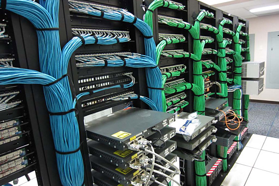
Performance, or increased speed, is likely the first enhancement that comes to mind, but performance improvements are not the only advantage 10GbE brings to data centers. It also unifies and simplifies the data center, thus reducing cost and complexities associated with maintaining the network. From the very beginning, simplicity and low cost were goals for Ethernet. And indeed, by unifying the data center storage and network fabrics by adding support for both Fibre Channel or iSCSI technologies over Ethernet and thus a single, low cost, high bandwidth interconnect, 10GbE is able to reduce network costs. In addition, 10GbE simplifies the network infrastructure by reducing power, improving bandwidth, and lessening cabling complexity.

As enticing as these advantages are, few technologies are compelling without a comprehensive ecosystem behind them. Ecosystems for new technologies can sometimes be a chicken and egg cycle, however. Vendors are reluctant to invest resources in building an ecosystem if enterprises aren’t buying product, but enterprises are reluctant to buy a new type of product if it lacks an ecosystem. A comprehensive ecosystem is an indicator of a technology’s maturity, and 10GbE does not disappoint.

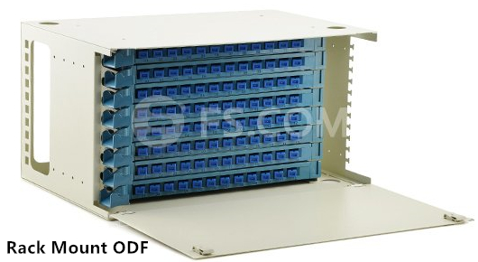
On the market today are a variety of products that support 10GbE, including processors, servers, adapters, switches, and cables. There is also support for multiple media types within 10GbE as well as improved cable technologies.

Getting the Most Out of Popular Technologies

For a technology improvement to be considered worth pursuing, it must facilitate the enterprise in more easily achieving its business goal. In the case of 10GbE, virtualization was the first technology to truly feel its benefits. Virtualization enables enterprises to satisfy a host of business goals from resource maximization to agility. The benefits virtualization brings to enterprises are enhanced and fully realized when the network is migrated to 10GbE.

Virtualization was, in effect, the watershed use case for 10GbE. It offered a way to address the growing complexity and bottlenecks associated with virtualization’s need for more network bandwidth. Now, IT could consolidate the ever-growing numbers of 1GbE ports and replace them with 10GbE. The move to 10GbE also enabled IT to unify data center storage and network fabrics, and in some cases I/O virtualization, by adding support for Fibre Channel or iSCSI technologies over Ethernet.

For many enterprises, the next stage after deploying a virtual infrastructure is to add a cloud component. This transition enables enterprises to not only scale resources for a specific application, but also, and more importantly, for the data center to scale to meet dynamic business needs.

For this to be successful, both storage and networking resources must move away from the restrictions endemic to dedicated hardware and be virtualized. This next step creates a virtual infrastructure that can be controlled and managed independent of the physical underlying compute, network, and storage infrastructure in the form of network virtualization and an SDN. For these infrastructures to function, the low latency of 10GbE, and in some cases 40GbE, is required.

Cloud and virtualization are not the only technologies driving 10GbE adoption. Rapidly increasing volumes of data, both structured and unstructured, must be stored and backed up. Being able to scale workloads quickly and efficiently by creating a single storage and data network, and enabling unified resource pools of compute and storage resources, is critical for the network to function at the speeds and capacities enterprises expect.

10GbE makes this possible.

10GbE Worldwide

Conclusion

10GbE enables enterprises to boost network performance while simplifying network infrastructure, reducing power, improving bandwidth, and reducing cabling complexity. Unifying different types of traffic onto a single, low-cost, high-bandwidth interconnect further simplifies the network.

The performance improvements and benefits of simplification and unification will be most acutely felt by enterprises deploying a virtual infrastructure. With a virtual infrastructure fast becoming the norm for many enterprises, the importance of a network that can meet performance, maintenance and other usability challenges is critical. In addition to virtualization, 10GbE offers numerous benefits to cloud-based infrastructures and enterprises with heavy storage requirements.