High-density Cabling With MTP/MPO Connectors

With the expected increase in use of 40 Gbps and 100 Gbps, there is an increasing demand for higher and higher density fiber cabling solutions. Existing and emerging network technologies are driving the need for increased data rates and fiber usage in the data center. High-density cabling with MTP/MPO connectors is essential to address these trends to provide an easy migration from duplex fiber serial transmission to 12- and 24-fiber parallel optics transmission.

What Is MTP / MPO Connector

The MPO connector is a multi-fiber connector defined according to IEC 61754-7 and TIA/EIA 604-5 that can accommodate up to 72 fibers in the tiniest of spaces, comparable to an RJ45 connector. MPO connectors are most commonly used for 12 or 24 fibers. To achieve lower tolerances and better attenuation values, the US Conec developed the MTP connector which has better optical and mechanical quality than the MPO. MTP/MPO connectors provide the following benefits:

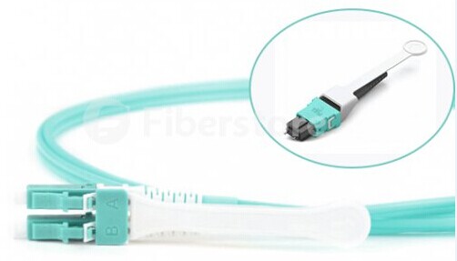
  • A single 12 fiber connector at one end connects to multiple duplex connectors at the other end such as LC or SC
  • Linking cables can be pre-connected to modules which are then placed in patch panels above the equipment
  • Modules can be replaced and upgraded if required
  • Scalable and adaptive to technology changes
  • Module can be replaced with a fan-out and adapter plate if required
MTP / MPO Cable Assemblies

Since field termination is becoming widely available, MTP/MPO technology and MTP/MPO cable assemblies listed below are becoming more and more popular.

MTP / MPO Trunk Cable

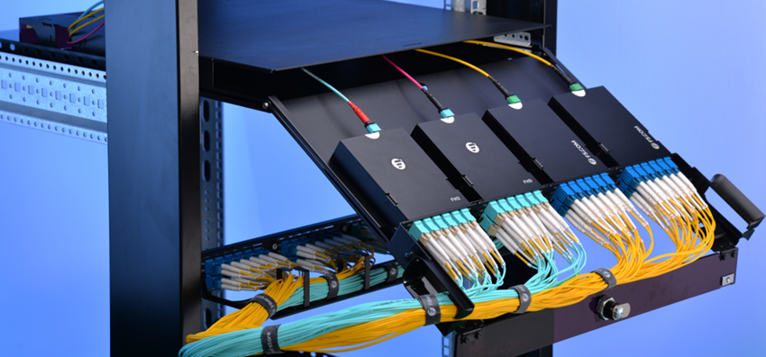
MTP/MPO trunk cables are terminated with the MTP/MPO connectors. Trunk cables are available with 12, 24, 48 and 72 fibers. MTP/MPO trunk cables are designed for data center applications. The plug and play solutions uses micro core cable to maximize bend radius and minimize cable weight and size.

MTP / MPO Cable Harness

MTP / MPO cable harness is also called MTP / MPO breakout cable or MTP / MPO fan-out cable. This cable has a single MTP connector on one end That breaks out into 6 or 12 connectors (LC, SC, ST, etc.). The MTP / MPO harness assembly has Become a popular method for connections into high-port-count network switches.

Push-Pull MTP / MPO Patch Cable

A push and pull cable has the same components and internal-structure as the traditional patch cords, except a tab attached to the connector used for pushing or pulling the whole connector. This small push-pull tab looks simple but it is functional for high density cabling in 40/100G migration. The Push-Pull MTP/MPO patch cable for highest density allows high-density MTP presentation underneath SAN switches or proximate to super computers. It also provides access to 192 MTP connections in 2U of height space.

push-pull-patch-cords

The Trend for High-density Cabling

MTP/MPO style pre-terminated cables offer a market-leading low loss, fast and efficient connection system particularly suited to the data center and storage area network environment. The following factors lead to the trend for high-density cabling:

  • Reduced cable size and increased air-flow to equipment
  • High Density blade servers with hundreds of ports
  • Virtualisation and cloud-computing
  • High real-estate costs for rack space
  • Reduced installation times
  • Structured cabling approach (zone approach)
  • 40G and 100G parallel optics

Fiberstore offers you a wide selection of MTP/MPO style pre-terminated cables including MTP/MPO trunk cable, MTP/MPO harness cable, Push-Pull MTP/MPO patch cable. Besides, we also provide Push-Pull tab LC patch cord and other related fiber cables. All these cables are with high flexibility and reliability. They can be customized according to your special requirements.

10 Gigabit Ethernet Cabling Options in Data Center

10 Gigabit Ethernet or 10GbE is a group of computer networking technologies for transmitting Ethernet frames at a rate of 10 gigabits per second. Nowadays, 10 Gigabit Ethernet is gaining broader deployments by the increasing bandwidth requirements and the growth of enterprise applications. In the world of 10 Gigabit Ethernet, selecting the appropriate 10-gigabit physical media is a challenge, because 10GbE is offered in two broad categories: optical and copper. This article will introduce both optical and copper cabling options for 10 Gigabit Ethernet.

Fiber Optical Cabling

Single-mode fiber (SMF), typically with an optical core of approximately 9 μm (microns), has lower modal dispersion than multimode fiber. It is able to support distances of at least 10 km, depending on transmission speed, transceivers and the buffer credits allocated in the switches. While multimode fiber (MMF), with an optical core of either 50 μm or 62.5 μm, can support distances up to 600 m, depending on transmission speed and transceivers.

When planning data center cabling requirements, be sure to consider that a service life of 15-20 years can be expected for fiber optic cabling. Thus the cable chosen should support legacy, current and emerging data rates.

10GBASE-SR — a port type for multimode fiber, 10GBASE-SR cable is the most common type for fiber optic 10GbE cable. It is able to support an SFP+ connector with an optical transceiver rated for 10GbE transmission speed. 10GBASE-SR cable is known as “short reach” fiber optic cable.

10GBASE-LR — a port type for single-mode fiber, 10GBASE-LR cable is the “long reach” fiber optic cable. It is able to support a link length of 10 km.

OM3 and OM4 are multimode cables that are “laser optimized” and support 10GbE applications. The transmission distance can be up to 300 m and 400 m respectively.

Copper Cabling

Common types of 10GbE copper cables are as follows:

  • 10GBASE-CR — the most common type of copper 10GbE cable, 10GBASE-CR cable uses an attached SFP+ connector and it is also known as a SFP+ direct attach copper (DAC). This fits into the same form factor connector and housing as the fiber optic cables with SFP+ connectors. Many 10GbE switches accept cables with SFP+ connectors, which support both copper and fiber optic cables.
  • Passive and Active DAC — passive copper connections are common with many interfaces. As the transfer rates increase, passive copper does not provide the distance needed and takes up too much physical space. So the industry is moving towards an active copper type of interface for higher speed connections. Active copper connections include components that boost the signal, reduce the noise and work with smaller gauge cables, improving signal distance, cable flexibility and airflow.
  • 10GBASE-T — 10GBASE-T cables are Cat6a (category 6 augmented). Supporting the higher frequencies required for 10GbE transmission, category 6a is required to reach the distance of 100 m (330 feet). Cables must be certified to at least 500 MHz to ensure 10GBASE-T compliance. Cat 6 cables may work in 10GBASE-T deployments up to 55 m (180 feet) depending on the quality of installation. Some 10GbE switches support 10GBASE-T (RJ45) connectors. 10GBASE-T offers the most flexibility, the lowest cost media, and is backward-compatible with existing 1 GbE networks.
Fiberstore Solutions for 10 Gigabit Ethernet

As one of the most professional optical manufacturers in China, Fiberstore’s solutions for 10 Gigabit Ethernet include 10G SFP+ fiber, 10G SFP+ DAC. Besides, we also supply high quality 10G transceivers, like X2-10GB-SR, SFP-10G-ZR, SFP-10G-SR, XFP-10GZR-OC192LR, etc.

Three Ways to Optimize Your Home Wireless Network

Nowadays, the home wireless network has grown significantly, which has brought a lot of convenience to people because of its fast and reliable features. But the world is not always perfect. When the signal keeps dropping or the speed is so slow, people might get frustrated. As a result, there has been a trend that people are more and more focusing on the speed of the network. This paper will give you some advice to optimize your home wireless network.

Organize Your Connected Devices

The easiest and most important way to optimize the home wireless network is to organize your connected devices in a structured media enclosure serve as the central hub. This enclosure can be the best housing for all of your devices, including routers, switches and modems, which can save you valuable space so that eliminate clutter and have easy access to all of your connected devices, all while maintaining a clean aesthetic. What is more, when you put your enclosure in the center of your home, your network connection coverage can be up to maximum. Remember that keep your access points off the floor, out of closets and cabinets, and away from walls and large metal objects, like file cabinets.

Check Your Network Devices

Check your network devices to make sure if they can still support the speed. You know, the technology is always advancing, so maybe it’s time to replace your old devices. For example, you can check the network adapter in your wireless devices such as computers or phones, to see if they use the 802.11n (wireless-N) protocol. If “Yes”, you can get the fastest speeds. But if your devices use the 802.11g protocol, it can be limited to wireless-G speeds (maximum 54 Mbps).

Also, you should know that the fewer devices on a wireless network, the faster the network is likely to run. So you can connect some of your equipment by a hardwired connection such as CAT cabling.

Change Channel Width

In order to adapt to the further advanced wireless protocols, one of the ways to increase the speed is using wider wireless channels. In general, if you want to achieve maximum speed, the routers should use a 40Mhz channel width. But the fact is that most routers come with 20MHz as the default width, which is in an attempt to avoid interference. This situation may be a potential negative affect on some users. If you start to notice issues, switch back to a 20Mhz operation. Also note that this isn’t really for increasing how fast you browse the internet. This change is more likely to be evident when streaming/transferring files between devices on your network. For this case, you can just find the “Channel Width” setting in your router’s setting and change it to “Auto 20/40MHz”.

Conclusion

After reading the above steps, it would be of some help to build your home wireless network. If you do check your devices or want to do some hardwired connections, you could visit FS.COM for help. It can offer the CAT cables and other telecommunication equipment with good quality and reasonable price, and you can pick up what you want. For more information, visit FS.COM.

Originally published at http://www.chinacablesbuy.com/three-ways-to-optimize-your-home-wireless-network.html

What are the Advantages and Disadvantages of Fiber Optic Cabling

Fiber optic cabling consists of strands of purified glass, or even plastic, rods that conduct specific wavelengths of light, analogous to the electrons carried along a Copper Ethernet Cable. However, light traveling through glass or plastic is not susceptible to the same problems that metal conductors are; The electromagnetic radiation that results from current traveling through a wire is not present in optical conductors, and optical conductors can be made much smaller than metal ones. Today, we’ll talk about the advantages and disadvantages of fiber optic cable.

advantages and disadvantages of fiber optic cable

Advantages and Disadvantages of Fiber Optic Cable

Everything has its own advantages and disadvantages. Learning the advantages and disadvantages of fiber optic cable, we may know how to select one when buying the cables.

Advantages

There are four advantages of fiber optic cabling, these advantages explain why fiber is becoming the preferred network cabling medium for high bandwidth, long-distance applications:

1. Immunity to Electromagnetic Interference (EMI)

All copper cable network media sharing a common problem: they are susceptible to electromagnetic interference (EMI), fiber optic cabling is immune to crosstalk because optical fiber does not conduct electricity and uses light signals in a glass fiber, rather than electrical signals along a metallic conductor to transmit data. So it cannot produce a magnetic field and thus is immune to EMI.

2. Higher Possible Data Rates

Because light is immune to interference, can be modulated at very high frequencies, and travels almost instantaneously to its destination, much higher data rates are possible with fiber optic cabling technologies than with traditional copper systems. Data rates far exceeding the gigabit per second (Gbps) range and higher are possible, and the latest IEEE standards body is working on 100Gbps fiber based applications over much longer distances than copper cabling. Multimode is preferred fiber optic type for 100-550 meters seen in LAN network, and since single mode fiber optic cables are capable of transmitting at these multi-gigabit data rates over very long distances, they are the preferred media for transcontinental and oceanic applications.

3. Longer Maximum Distances

Typical copper media data transmission by the distance limits the maximum length of less than 100 meters. Because they do not suffer from the electromagnetic interference problems of traditional copper cabling and because they do not use electrical signals that can dramatically reduce the long distance, single-mode fiber optic cables can span 75 kilometers (about 46.6 miles) without using signal-boosting repeaters.

4. Better Security

The Copper cable transmission media is susceptible to eavesdropping through taps. A tap (short for wiretap) is a device that punctures through the outer jacket of a copper cable and touches the inner conductor. The tap intercepts signals sent on a LAN and sends them to another (unwanted) location. Electromagnetic (EM) taps are similar devices, but rather than puncturing the cable,they use the cable’s magnetic fields, which are similar to the pattern of electrical signals. Because fiber optic cabling uses light instead of electrical signals, it is immune to most types of eavesdropping. Traditional taps won’t work because any intrusion on the cable will cause the light to be blocked and the connection simply won’t function. EM taps won’t work because no magnetic field is generated. Because of its immunity to traditional eavesdropping tactics, fiber optic cabling is used in networks that must remain secure, such as government and research networks.

Disadvantages

With all of its advantages, many people use fiber optic cabling. However, fiber optic cabling does have a couple of disadvantages:

1. Higher Cost

The higher cost of fiber optic cabling has little to do with the cable these days. Increases in available fiber optic cable manufacturing capacity have lowered cable prices to levels comparable to high end UTP on a per-foot basis, and the cables are no harder to pull. Ethernet hubs, switches, routers, NICs, and patch cords for UTP are very inexpensive. A high quality UTP-based 10/100/1000 auto-sensing Ethernet NIC for a PC can be purchased for less than $25. A fiber optic NIC for a PC costs at least four times as much. Similar price differences exist for hubs, routers, and switches. For an IT manager who has several hundred workstations to deploy and support, that translates to megabucks and keeps UTP a viable solution. The cost of network electronics keeps the total system cost of fiber-based networks higher than UTP, and ultimately, it is preventing a mass stampede to fiber-to-the-desk.

2. Installation

The other main disadvantage of fiber optic cabling is that it can be more difficult to install. Ethernet cable ends simply need a mechanical connection, and those connections don’t have to be perfect. Fiber optic cable can be much trickier to make connections for mainly because of the nature of the glass or plastic core of the fiber cable. When you cut or cleave (in fiber optic terms) the fiber, the unpolished end consists of an irregular finish of glass that diffuses the light signal and prevents it form guiding into the receiver correctly. The end of the fiber must be polished and a special polishing tools to make it perfectly flat so that the light will shine through correctly.

Conclusion

From the above, we have learnt the advantages and disadvantages of fiber optic cable. Knowing the advantages and disadvantages of fiber optic cable can help us to choose a suitable fiber cable. For more details about fiber cables, please visit FS.COM.

Related Articles:
Multimode Fiber Types: OM1 vs OM2 vs OM3 vs OM4 vs OM5
Single Mode vs Multimode Fiber: What’s the Difference?