The Role of OM5 and MTP Fiber in 40GbE and Beyond

In order to meet the overwhelming trend of growing bandwidth, different standards for single-mode and multimode fibers are published, and parallel fiber connector (MTP/MPO) is designed to solve the problem of increasing fiber count. Though the fiber types are changing, the use of the parallel connector seems not to be outdated, not only for present 40G and 100G applications, but also for future 200G and 400G. This post will discuss the issue on a new fiber type and the role of parallel fiber in 40GbE and beyond networks.

Overview on Multimode and Single-mode Fibers

Since the establishment of multimode fiber in the early 1980s, there has been OM1 and OM2, and laser optimized OM3 and OM4 fibers for 10GbE, 40GbE and 100GbE. OM5, the officially designated wideband multimode fiber (WBMMF), is a new fiber medium specified in ANSI/TIA-492AAAE. The channel capacity of multimode fiber has multiplied by using parallel transmission over several fiber strands. In terms of single-mode fiber, there are only OS1 and OS2; and it has been serving for optical communications without much change for a long time. Compared with the constant updates of multimode fiber and considering other factors, some enterprise customers prefer to use single-mode fiber more over the past years and for the foreseeable future. With the coming out of the new OM5 fiber, it seems that multimode fiber might last for a longer time in the future 200G and 400G applications.

The Issue on the Upcoming Fiber Type

The new fiber medium OM5 is presented as the first laser-optimized MMF that specifies a wider range of wavelengths between 840 and 953 nm to support wavelength division multiplexing (WDM) technology (at least four wavelengths). It is also specified to support legacy applications and emerging short wavelength division multiplexing (SWDM) applications. Although OM5 has been anticipated to be “performance compliant and superior to OM4” based on the following parameters, there are still some arguments on the statement that OM5 is a better solution for data centers.

OM4 & OM5 comparison

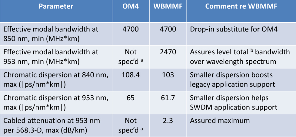
Figure 1: OM4 and OM5 comparison.

OM5 supporters talk about the problems of present multimode fibers in long-term development. The opinion holds that the future 400GBASE-SR16 which will reuse 100GBASE-SR4 technology specified in IEEE 802.3bs Standard draft, calls for a new 32 fibers 2-row MTP/MPO connector instead of a 12 fibers MTP/MPO connector. It will be hard for current structured cabling that uses MTP-12 to move to MTP-16 requirements.

12f MTP connector (left) and 32f MTP connector (right).
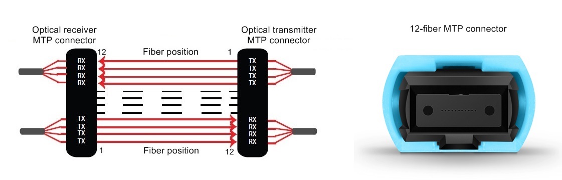
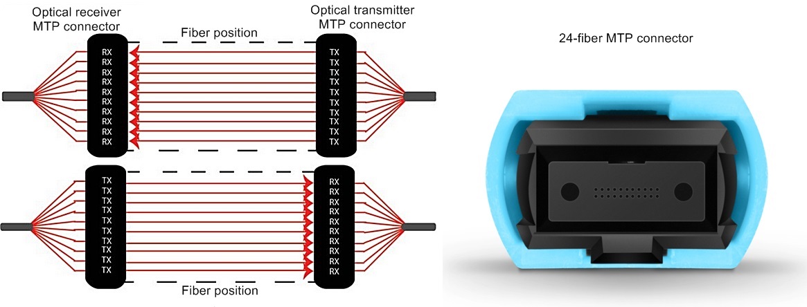
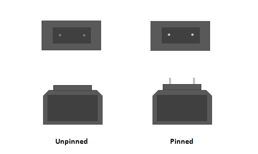
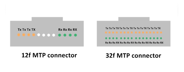
Figure 2: 12f MTP connector (left) and 32f MTP connector (right).

However, the OM5 fiber solution, which can support 4 WDM wavelengths, will enable 4 fiber count reduction in running 40G, 100G and 200G using duplex LC connections. Combined with parallel technology, 400G can also be effectively transmitted over OM5 fibers using only 4 or 8 fibers.

40G, 100G, 200G, and 400G WDM transmission over OM5 fiber

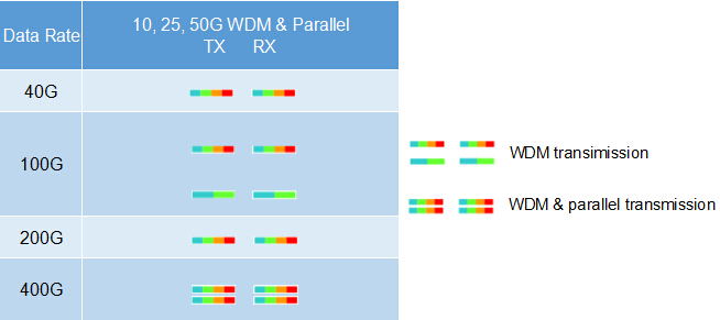
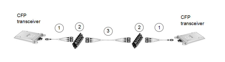
Figure 3: 40G, 100G, 200G, and 400G WDM transmission over OM5 fiber.

On the other side, some people don’t support the idea that OM5 is a good solution for future 400G network. They argue that OM5 isn’t that optimized than current MMF types. The first reason is that for all the current and future multimode IEEE applications including 40GBASE-SR4, 100GBASE-SR4, 200GBASE-SR4, and 400GBASE-SR16, the maximum allowable reach is the same for OM5 as OM4 cabling.

MMF-Standard-Specifications-1

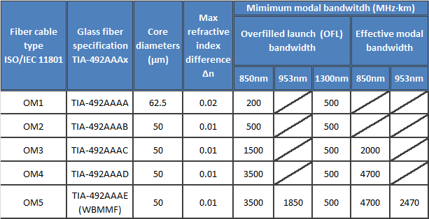
Figure 4: Multimode fiber standard specifications.
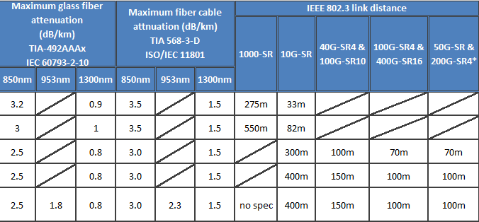
MMF-Standard-Specifications-continued

Figure 4 continued.

The second reason is that, even by using SWDM technology, the difference on the reaches for OM4 and OM5 in 40G and 100G is minimal. For 40G-SWDM4, OM4 could support a 400-meter reach and OM5 a 500-meter reach. For 100G-SWDM4, OM4 could support 100 meters and OM5 is only 50 meters more than OM4.

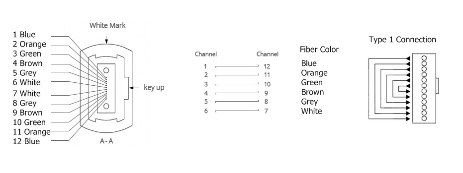
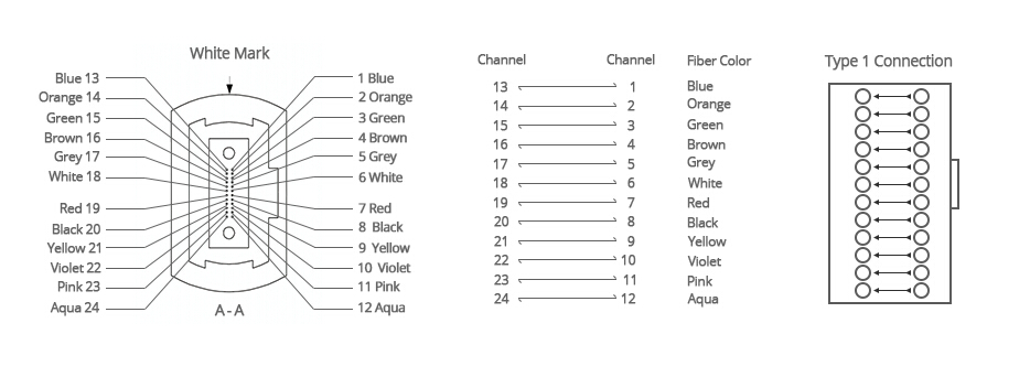
And thirdly, the PAM4 technology can increase the bandwidth of each fiber from 25G to 50-56G, which means we can stick to current 12-fiber and 24-fiber MTP/MPO connectors as cost-effective solutions in the 40G, 100G and beyond applications.

Conclusion

The options for future higher speed transmission are still in discussion, but there is no doubt that no matter we choose to use new OM5 fiber or continue to use single-mode fiber and OM3/OM4 fiber, the “parallel fibers remain essential to support break-out functionality” as stated in WBMMF standardization. It is the fact that parallel fiber solution enables higher density ports via breakout cabling and reduces cost per single-lane channel.

CMR, CMP and LSZH MTP/MPO Cable

Multifiber MTP/MPO cable is a preferable choice for high-density telecom and datacom cabling. For the outer jacket of MTP/MPO cable, there are many terms to describe it, such as CM, LSZH, CMP, CMR, PVC, etc. FS.COM carries several of these technologies. Do you know the differences between them? And what are the characteristics of each type? Most importantly, which one do you need for the task? This post will introduce some major jacket types for MTP/MPO cable and the other acronyms for communication cable ratings.

MTP cabling

Figure 1: MTP/MPO cabling.

CMP

CMP (plenum-rated) MTP/MPO cable complies the IEC (International Electrotechnical Commission) 60332-1 flammability standard. CMP MTP/MPO cable is designed to be used in plenum spaces, where air circulation for heating and air conditioning systems can be facilitated, by providing pathways for either heated/conditioned or return airflows. Typical plenum spaces are between the structural ceiling and the drop ceiling or under a raised floor. CMP rated communication cable is suitable for telephone and computer network exactly for this matter. It is designed to restrict flame propagation no more than five feet, and to limit the amount of smoke emitted during fire. Additionally, CMP MTP/MPO cable is more fire-retardant than LSZH, and as a result, sites are better protected. As an excellent performer cable, it is usually more costly than other cable types.

It has to be noted that some CMP cable made of fluorinated ethylene polymer (FEP) still has shortcomings of potential toxicity. Thus better CMP cable with a non-halogen plenum compound is further produced. For safety reason, no high-voltage equipment is allowed in plenum space because presence of fresh air can greatly increase danger of rapid flame spreading if the equipment catch on fire.

LSZH

The LSZH (low smoke zero halogen, also refers to LSOH or LS0H or LSFH or OHLS) has no exact IEC code equivalent. The LSZH cable is based on the compliance of IEC 60754 and IEC 61034. LSZH MTP/MPO cable is better than other cables in been safer to people during a fire. It has no halogens in its composition and thus does not produce a dangerous gas/acid combination when exposed to flame. LSZH cable reduces the amount of toxic and corrosive gas emitted during inflammation. LSZH MTP/MPO cables are suitable to be used in places that is poorly aired such as aircraft, rail cars or ships, to provide better protection to people and equipment. LSZH MTP/MPO cable is more widely applied type than other materials, both for its secure properties and lower cost than CMP.

Other Types

The cable jackets will be discussed in the following part are not as frequently used for MTP/MPO cable as CMP and LSZH.

CMR (riser-rated) complies IEC 60332-3 standards. CMR cable is constructed to prevent fires from spreading floor to floor in vertical installations. It can be used when cables need to be run between floors through risers or vertical shafts. PVC is most often associated with riser-rated cable, but nor all PVC cable is necessarily riser-rated; FEP is most often associated with CMP. Since the fire requirements for CMR cable is not that strict, CMP cable can always replace CMR cable, but not reversibly.

CM (in-wall rated) cable is a general purpose type, which is used in cases where the fire code does not place any restrictions on cable type. Some examples are home or office environments for CPU to monitor connections.

The figure below generally illustrates the applicable environments for CMP, CMR and CM rated cables.

CMP, CMR, CM cable application

Figure 2: CMP, CMR, CM cable application.

Conclusion

Knowing the relevant details of cable ratings of MTP/MPO will certainly help in selecting the best one for your applications, which is as important as other factors. FS.COM provides high quality plenum and LSZH MTP/MPO trunk cables and MTP breakout cables at affordable prices.

Connectivity Solutions for Duplex and Parallel Optics

In optical communication, duplex and parallel optical links are two of the most commonly deployed cabling structures. This post will discuss some specific connectivity solutions using 2-fiber duplex and 8-fiber/20-fiber parallel fiber optic modules.

Duplex and Parallel Optical Links

A duplex link is accomplished by using two fibers. The most commonly used connector is the duplex LC. The TIA standard defines two types of duplex fiber patch cables terminated with duplex LC connector to complete an end-to-end fiber duplex connection: A-to-A patch cable (a cross version) and A-to-B patch cable (a straight version). In this article the LC to LC duplex cables we use are all A-to-B patch cables. It means the optical signal will be transmitted on B connector and received on A connector.

two types of duplex-patch-cable

Figure 1: two types of fiber patch cables

A parallel link is accomplished by combining two or more channels. Parallel optical links can be achieved by using eight fibers (4 fibers for Tx and 4 fibers for Rx), twenty fibers (10 fibers for Tx and 10 fibers for Rx) or twenty-four fibers (12 fibers for Tx and 12 fibers for Rx). To accomplish an 8-fiber optical link, the standard cabling is a 12-fiber trunk with an MTP connector (12-fiber connector). It follows the Type B polarity scheme. The connector type and the alignment of the fibers is shown in figure 2.

8-fiber parllel system

Figure 2: parallel fiber (8-fiber) optic transmission

To accomplish a 20-fiber parallel optical link, a parallel 24-fiber MTP connector is used. Its fiber alignment and connector type is shown in figure 3.

20-fiber parallel system

Figure 3: parallel fiber (20-fiber) optic transmission
Duplex Fiber Optic Transmission Links (2-fiber to 2-fiber)

We will discuss the items required to connect two duplex transceivers in this part. These 2-fiber duplex protocols include but not limited to: 10GBASE-SR, 10GBASE-LR, 10GBASE-ER, 40GBASE-BiDi, 40GBASE-LR4, 40GBASE-LRL4, 40GBASE-UNIV, 40GBASE-FR, 100GBASE-LR4, 100GBASE-ER4, 100GBASE-CWDM4, 100GBASE-BiDi, 1GFC, 2GFC, 4GFC, 8GFC, 16GFC, 32GFC.

Duplex Direct Connectivity

When directly connecting two duplex SFP+ transceivers, an A-to-B type patch cable is required. This type of direct connectivity is suggested only to be used within a given row of racks/cabinets. Figure 4 shows two SFP+s connected by one LC to LC duplex patch cable.

2-fiber to 2-fiber direct connectivity Figure 4: 2-fiber to 2-fiber direct connectivity

Duplex Interconnect

The following figure is an interconnect for two duplex transceivers. An 8-fiber MTP trunk cable is deployed with 8-fiber MTP-LC breakout modules connected to the end of the trunk. It should be noted that the polarity has to be maintained during the transmission. And pinned connectors should be deployed with unpinned devices. Structured cabling allows for easier moves, adds, and changes (MACs). Figure 5 illustrates this solution.

2-fiber to 2-fiber interconnect (1)

Figure 5: 2-fiber to 2-fiber interconnect (1)

Item Description
1 LC to LC duplex cable (SMF/MMF)
2 MTP-8 to duplex LC breakout module (pinned)
3 8 fibers MTP trunk cable (not pinned)

Figure 6 is also an interconnect solution for SFP+ transceivers, but on the right side an 8-fiber MTP to 4 x LC harness cable and an MTP adapter panel are used instead. This solution works best when connectivity is required for high port count switch.

2-fiber to 2-fiber interconnect (2)

Figure 6: 2-fiber to 2-fiber interconnect (2)

Item Description
1 LC to LC duplex cable (SMF/MMF)
2 MTP-8 to duplex LC breakout module (pinned)
3 8 fibers MTP trunk cable (not pinned)
4 96 fibers MTP adapter panel (8 port)
5 8 fibers MTP (not pinned) to duplex 4 x LC harness cable
Duplex Cross-Connect

This solution is a duplex cross-connect. It will allow all patching to be made at the main distribution area (MDA) with maximum flexibility for port-to-port connection. Figure 7 illustrates the cross-connect solution for duplex connectivity.

2-fiber to 2-fiber cross-connect

Figure 7: 2-fiber to 2-fiber cross-connect

Item Description
1 LC to LC duplex cable (SMF/MMF)
2 MTP-8 to duplex LC breakout module (pinned)
3 8 fibers MTP trunk cable (not pinned)
Parallel Fiber Optic Transmission Links

We will discuss items required to connect two parallel (8-fiber or 20-fiber) transceivers in this part. These protocols include but not limited to: 40GBASE-SR4, 40GBASE-xSR4/cSR4/eSR4, 40GBASE-PLR4, 40GBASE-PSM4, 100GBASE-SR4, 100GBASE-eSR4, 100GBASE-PSM4, 100GBASE-SR10.

Parallel Direct Connectivity (8-fiber or 20-fiber)

When directly connecting two QSFP+ or QSFP 28 transceivers, an 8-fiber MTP trunk cable is needed. For directly connecting two CFP transceivers, a 24-fiber MTP trunk cable is needed.

8-fiber to 8-fiber direct connectivity

Figure 8: 8-fiber to 8-fiber direct connectivity
Parallel Interconnect (8/20-fiber)

Figure 9 shows an interconnect solution for two CFP modules (20-fiber). To break-out the CFPs to transmit the signal across an 8-fiber infrastructure, a 1 x 3 breakout harness (24-fiber MTP to three 8-fiber MTP) is required. To achieve an interconnect for two 8-fiber optics, we can replace the breakout harness by an 8-fiber MTP (pinned) trunk and the 24-fiber MTP trunk by an MTP (not pinned) trunk.

20-fiber to 20-fiber interconnect

Figure 9: 20-fiber to 20-fiber interconnect

Item Description
1 1×3 MTP breakout harness cable (24-fiber MTP to three 8-fiber MTP) (pinned)
2 96 fibers MTP adapter panel (8 ports)
3 24 fibers MTP trunk cable, three 8-fiber legs (not pinned)
Conclusion

This post gives brief introduction to the meaning of duplex and parallel optical link and presents some connectivity solutions for two duplex optics or two parallel optics. The corresponding items used in each solution are listed too. The transmission distance and working environment should be taken into account when applying each cabling solution. The parallel to duplex connectivity solutions will be discussed in the next post.

Things We Should Know Before Migrating to Base-8 System

Since the introduction of Base-12 connectivity in the mid 1990s, the 12-fiber MTP/MPO connector and Base-12 connectivity have served the data center for about twenty years. It has helped a lot in achieving high-density and manageable cabling. Recently, many documents and posts are discussing about a new technology—Base-8. Its appearance is regarded as the evident need of future networks. Even though most of the words are promoting the overwhelming advantages of Base-8 system, we should still consider the defects and merits of these two systems based on some facts before taking the next step by ourselves. This post is a discussion on this topic.

Facts of Base-12 and Base-8

In this part, the design features of Base-12 and Base-8 systems will be introduced. And their dominant advantages are going to be discussed too.

Design Features

Base-12 connectivity makes use of links based on groups of 12, with 12-fiber connectors such as the MTP. In Base-12 connectivity, for example, trunk cables have fiber counts that are divisible by number 12, like 24-fiber trunk cable, 48-fiber trunk cable and all the way up to 144 fibers. However, in a Base-8 system, we don’t have 12-fiber trunk cable, instead we have 8-fiber trunk cable, 16-fiber trunk cable, 32-fiber trunk cable and so on. All trunk cables are based on increments of 8 fibers.

Base-12 and Base-8 trunk cables are visually different on connector design. A Base-12 trunk cable generally has unpinned (female) connectors on both ends and demands the use of pinned breakout modules. In the new emerging Base-8 system, a trunk cable is designed with pinned (male) connectors, as a result, it should be connected to unpinned components.

pinned & unpinned connectors
Figure: Unpinned Connector and Pinned Connector
Comparison

Compared with Base-8, Base-12 obviously has the benefit of higher connector fiber density. Thus a larger number of fibers can be installed more quickly when using Base-12 connectivity. And it is very easy to be deployed into all-ready existing Base-12 architecture. As the networks are migrating to 40G and 100G data speeds, Base-8 connectivity has some advantages that cannot be denied. For some 40G and 100G applications, including SR4 (40G and 100G over parallel MMF) and PSM4 (100G over parallel SMF) supported eight-fiber transceivers, and SAN switch Base-8/Base-16 port arrangements, Base-8 connectivity is a more cost-effective choice. In these applications, Base-8 enables full fiber utilization for eight-fiber transceiver systems. But Base-8 connectivity is not optimized for all situations, including duplex protocols like 25G and 100G (duplex SMF).

Correct Co-existence of Base-8 and Base-12

If we are going to deploy Base-8 devices in our existing network, it is possible to have Base-12 and Base-8 connectivity at the same time as long as we do not mix them in the same link. On one hand, it is not wise to use conversion module between Base-12 and Base-8 devices, because the added cost and increased insertion loss will surpass the benefits it can brought. As mentioned before, the two systems are not interchangeable since they usually have different connector configurations and have unequal attachment requirements. Therefore, special care should be given when managing the data canter physical layer infrastructure, to ensure that the Base-12 and Base-8 components are used separately.

Conclusion

When a new technology comes out as a new option for us, we need to decide whether to change or not. In terms of the discussion on Base-12 and Base-8 systems, after listening to voices from different sides, the key factors are still determined by own specific needs. If we decided to move to the new technology, the following question is how to realize the best migration. Having comprehensive understanding of the solutions and products vendors supply will never be a bad choice.

Which Fiber Loopback Should I Use for My Transceiver?

In telecommunication, fiber loopback is a hardware designed to provide a media of return patch for a fiber optic signal, which is typically used for fiber optic testing or network restorations. When we need to know whether our fiber optic transceiver is working perfectly, we can use a fiber loopback cable as an economic way to check and ensure it. Basically, the loopback aids in debugging the physical connection problem of the transceiver by directly routing the laser signal from the transmitter port back to the receiver port. Since fiber optic transceivers have different interface types and connect different types of cables, it is not that simple to choose a right loopback for our transceiver. This post will be a guide on how to choose a right loopback cable for specific transceiver module.

Fiber Loopback Types and Configurations

Before deciding which loopback cable to use, we should firstly know the structure and classification of fiber loopback cable. Generally, a fiber loopback is a simplex fiber optic cable terminated with two connectors on each end, forming a loop. Some vendors provide improved structure with a black enclosure to protect the optical cable. This designing is more compact in size and stronger in use. Based on the fiber type used, there is single-mode loopback and multimode loopback, available for different polishing types. According to the optical connector type of the loopback, fiber loopback cables can be divided to LC, SC, FC, ST, MTP/MPO, E2000, etc. In testing fiber optic transceiver modules, the most commonly used are LC, SC and MTP/MPO loopback cables.

lc&sc loopback cable
Figure 1: LC & SC Loopback Cable

The LC and SC loopbacks are made with simplex fiber cable and common connectors; it’s not difficult to understand their configurations. As for the MTP/MPO loopback, it is mainly used for testing parallel optics, such as 40G and 100G transceivers. Its configuration varies since the fiber count is not always the same in different applications.

8 Fibers MTP/MPO Loopback Cable Configuration

In a 8 fibers MTP/MPO loopback, eight fibers are aligned on two sides of the connector, leaving the central four channels empty. And the fibers adopt a straight configuration of 1-12, 2-11, 5-8, 6-7. The polarity channel alignment is illustrated in the following figure.

8 Fibers Loopback Polarity Channel Alignment
Figure 2: 8 Fibers Loopback Polarity Channel Alignment
12 Fibers MTP/MPO Loopback Cable Configuration

The only difference between the 12-fiber MTP loopback and the 8-fiber loopback is that the central four channels are not empty. Its alignment is 1-12, 2-11, 3-10, 4-9, 5-8, 6-7.

12 Fibers Loopback Polarity Channel Alignment
Figure 3: 12 Fibers Loopback Polarity Channel Alignment
24 Fibers MTP/MPO Loopback Cable Configuration

The 24 fibers MTP loopback also adopts type 1 polarity. Its alignment design is shown below.

24 Fibers Loopback Polarity Channel Alignment
Figure 4: 24 Fibers Loopback Polarity Channel Alignment
Which to Choose for a Specific Transceiver?

Considering the common features of the transceiver and the loopback, we should think about the connector type, polish type, and cable type when selecting a loopback for the transceiver. The selection guide for some mostly used transceiver modules is summarized in the following tables.

Table 1: Loopback choices for 10G SFP+ transceivers

Model Interface type Cable Type Suited Loopback
10GBASE-USR LC Duplex (PC) MMF

LC/UPC Duplex Multimode Fiber Loopback

10GBASE-SR LC Duplex (UPC) MMF
10GBASE-LR LC Duplex (UPC) MMF
10GBASE-ER LC Duplex (UPC) SMF

LC/UPC Duplex Single-mode Fiber Loopback

10GBASE-ZR LC Duplex (PC) SMF

Table 2: Loopback choices for 40G QSFP+ transceivers

Model Interface type Cable Type Suited Loopback
40GBASE-CSR4 MTP/MPO (UPC) MMF

8/12 Fibers MTP/UPC Multimode Fiber Loopback

40GBASE-SR4 MTP/MPO (UPC) MMF
40GBASE-PLRL4 MTP/MPO (APC) SMF

8/12 Fibers MTP/APC Single-mode Fiber Loopback

40GBASE-PLR4 MTP/MPO (APC) SMF
40GBASE-LR4 LC Duplex (PC) SMF

LC/UPC Duplex Single-mode Fiber Loopback

40GBASE-LR4L LC Duplex (UPC) SMF
40GBASE-ER4 LC Duplex (UPC) SMF
40GBASE-LX4 LC Duplex (UPC) MMF/SMF

LC/UPC Duplex Multimode/Single-mode Fiber Loopback

Table 3: Loopback choices for 100G QSFP28 transceivers

Model Interface type Cable Type Suited Loopback
100GBASE-SR4 MTP/MPO (UPC) MMF

8/12 Fibers MTP/UPC Multimode Fiber Loopback

100GBASE-PSM4 MTP/MPO (APC) SMF

8/12 Fibers MTP/APC Single-mode Fiber Loopback

100GBASE-LR4 LC Duplex (UPC) SMF

LC/UPC Duplex Single-mode Fiber Loopback

Table 4: Loopback choices for CFP transceivers

Model Interface type Cable Type Suited Loopback
40GBASE-SR4 CFP MPO/MTP (UPC) MMF

8/12 Fibers MTP/UPC Multimode Fiber Loopback

40GBASE-LR4 CFP SC Duplex (UPC) SMF

SC/UPC Duplex Single-mode Fiber Loopback

40GBASE-FR CFP SC Duplex (UPC) SMF
100GBASE-LR4 CFP SC Duplex(PC/UPC) SMF
100GBASE-ER4 CFP SC Duplex(PC/UPC) SMF
100GBASE-SR4 CFP MPO/MTP (UPC) MMF

24 Fibers MTP/UPC Multimode Fiber Loopback

Conclusion

This post discusses specific fiber loopback choices for some most commonly used fiber optic transceivers. For other transceiver modules that are not mentioned in this post, we can also know how to choose a suitable loopback for it by getting details about its interface type, physical contact and cable type.