PoE Switch vs. PoE Injector: Which One to Choose?

Network has become an essential part of our daily life. To make life easier, there are various types of network devices on the market, such as such as IP phone, wireless access point and IP camera. Each of them not only has to get access to the network through the Ethernet cable, but also needs power supply via power cord. When the number of devices is a little more, the cabling will be complicated. How to solve this problem? Recently, PoE (Power over Ethernet) technology is popular, which can transmit both power and data through an Ethernet cable at the same time. When it comes to PoE, there are two hot devices: PoE switch and PoE injector. And people often ask: PoE switch vs. PoE injector: which one to choose? This article will make a comparison between them and help you make the choice.

PoE Switch vs. PoE Injector: What is PoE Switch?

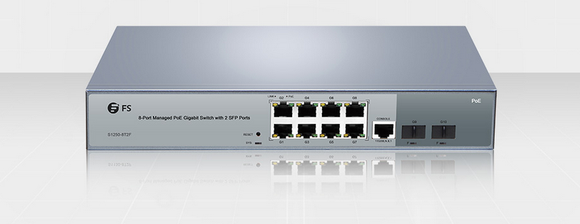
PoE switch is a network switch that has Power over Ethernet injection built-in. When connected with other network devices, PoE switch will detect whether they are PoE-compatible and enable power automatically. Therefore, it is a simple solution to add PoE to your network by using PoE switch. In addition, there is PoE+ switch available on the market. PoE switch utilizes the original PoE standard, IEEE 802.3af, which provides up to 15.4W of DC power to each device. While PoE+ switch use the latest PoE+ standard, IEEE 802.3at, also known as PoE class 4, which provides up to 30W of power to each device. That’s to say PoE+ switch can provide almost twice as much power as PoE switch. The following figure shows a 8-port PoE switch which is popular among many users.

best 8 port gigabit switch

PoE Switch vs. PoE Injector: What is PoE Injector?

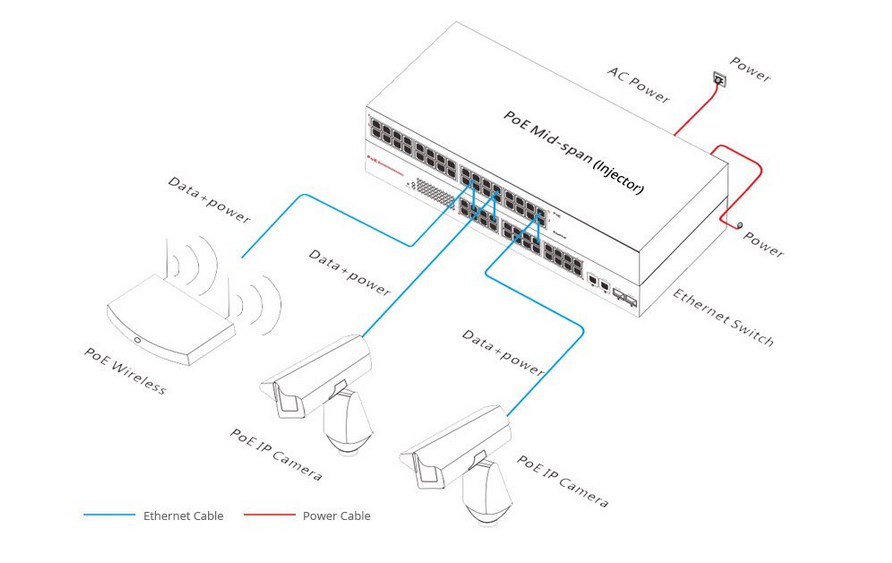
PoE injector is used to add PoE capability to regular non-PoE network links. The following figure shows the application of PoE injector. Both PoE injector and non-PoE Ethernet switch are powered on. Then they are connected by an Ethernet cable. By doing this, the PoE-compatible IP phone, wireless access point and IP camera can work through one Ethernet cable respectively connected to PoE injector. In network deployment, PoE injector can provide a versatile solution when fewer PoE ports are required.

PoE Switch Vs. PoE Injector

PoE Switch vs. PoE Injector: Which One to Choose?

PoE switch is all-in-one box with no additional appliance and the ports on it can be used to manage both network and power. While PoE injector can be added onto existing networks with no need to change the switch and is easy to mount anywhere. As for which one to choose, it really depends on the specific requirement. For example:

  • If you only have a few things to power, then PoE injectors are good. The cost is lower when compared to a PoE switch.
  • If the PoE goes out in a PoE switch, all PoE has the chance of going out. But if a PoE injector goes out, it only affects one device.
  • If you do have to replace a PoE injector, you can just replace the bad injector without any production downtime anywhere else in the network.

Conclusion

Both PoE switch and PoE injector utilize PoE technology which makes network deployment even simpler and have their own advantages. It is important to figure out what you need before you make a choice between them. What’s more, please ensure your device supports PoE before connecting into a PoE-enabled network. PoE Switch Vs. PoE Injector, hope this article is helpful for you.

Related Article: 8 Port PoE Switch Recommendations
Power over Ethernet Technology & PoE Switch Explained

The Role of OM5 and MTP Fiber in 40GbE and Beyond

In order to meet the overwhelming trend of growing bandwidth, different standards for single-mode and multimode fibers are published, and parallel fiber connector (MTP/MPO) is designed to solve the problem of increasing fiber count. Though the fiber types are changing, the use of the parallel connector seems not to be outdated, not only for present 40G and 100G applications, but also for future 200G and 400G. This post will discuss the issue on a new fiber type and the role of parallel fiber in 40GbE and beyond networks.

Overview on Multimode and Single-mode Fibers

Since the establishment of multimode fiber in the early 1980s, there has been OM1 and OM2, and laser optimized OM3 and OM4 fibers for 10GbE, 40GbE and 100GbE. OM5, the officially designated wideband multimode fiber (WBMMF), is a new fiber medium specified in ANSI/TIA-492AAAE. The channel capacity of multimode fiber has multiplied by using parallel transmission over several fiber strands. In terms of single-mode fiber, there are only OS1 and OS2; and it has been serving for optical communications without much change for a long time. Compared with the constant updates of multimode fiber and considering other factors, some enterprise customers prefer to use single-mode fiber more over the past years and for the foreseeable future. With the coming out of the new OM5 fiber, it seems that multimode fiber might last for a longer time in the future 200G and 400G applications.

The Issue on the Upcoming Fiber Type

The new fiber medium OM5 is presented as the first laser-optimized MMF that specifies a wider range of wavelengths between 840 and 953 nm to support wavelength division multiplexing (WDM) technology (at least four wavelengths). It is also specified to support legacy applications and emerging short wavelength division multiplexing (SWDM) applications. Although OM5 has been anticipated to be “performance compliant and superior to OM4” based on the following parameters, there are still some arguments on the statement that OM5 is a better solution for data centers.

OM4 & OM5 comparison

Figure 1: OM4 and OM5 comparison.

OM5 supporters talk about the problems of present multimode fibers in long-term development. The opinion holds that the future 400GBASE-SR16 which will reuse 100GBASE-SR4 technology specified in IEEE 802.3bs Standard draft, calls for a new 32 fibers 2-row MTP/MPO connector instead of a 12 fibers MTP/MPO connector. It will be hard for current structured cabling that uses MTP-12 to move to MTP-16 requirements.

12f MTP connector (left) and 32f MTP connector (right).
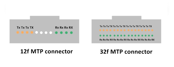
Figure 2: 12f MTP connector (left) and 32f MTP connector (right).

However, the OM5 fiber solution, which can support 4 WDM wavelengths, will enable 4 fiber count reduction in running 40G, 100G and 200G using duplex LC connections. Combined with parallel technology, 400G can also be effectively transmitted over OM5 fibers using only 4 or 8 fibers.

40G, 100G, 200G, and 400G WDM transmission over OM5 fiber

Figure 3: 40G, 100G, 200G, and 400G WDM transmission over OM5 fiber.

On the other side, some people don’t support the idea that OM5 is a good solution for future 400G network. They argue that OM5 isn’t that optimized than current MMF types. The first reason is that for all the current and future multimode IEEE applications including 40GBASE-SR4, 100GBASE-SR4, 200GBASE-SR4, and 400GBASE-SR16, the maximum allowable reach is the same for OM5 as OM4 cabling.

MMF-Standard-Specifications-1

Figure 4: Multimode fiber standard specifications.

MMF-Standard-Specifications-continued

Figure 4 continued.

The second reason is that, even by using SWDM technology, the difference on the reaches for OM4 and OM5 in 40G and 100G is minimal. For 40G-SWDM4, OM4 could support a 400-meter reach and OM5 a 500-meter reach. For 100G-SWDM4, OM4 could support 100 meters and OM5 is only 50 meters more than OM4.

And thirdly, the PAM4 technology can increase the bandwidth of each fiber from 25G to 50-56G, which means we can stick to current 12-fiber and 24-fiber MTP/MPO connectors as cost-effective solutions in the 40G, 100G and beyond applications.

Conclusion

The options for future higher speed transmission are still in discussion, but there is no doubt that no matter we choose to use new OM5 fiber or continue to use single-mode fiber and OM3/OM4 fiber, the “parallel fibers remain essential to support break-out functionality” as stated in WBMMF standardization. It is the fact that parallel fiber solution enables higher density ports via breakout cabling and reduces cost per single-lane channel.

How Can the Dispersion Be Compensated in Optical Communication?

In optical fiber communication, there are three factors that can degrade the optical signal during transmission. They are attenuation, dispersion and nonlinear effects. Among these problems, attenuation has been solved with the improvement of fiber manufacturing and the invention of erbium-doped fiber amplifier (EDFA). But dispersion affects the system most and is tougher to overcome compared with the other two factors. How can the dispersion be compensated in optical communication?

What Is Dispersion?

In fiber optical transmission, dispersion is defined as the pulse spreading in optical fiber. In order to explain this phenomenon in a plain way, the most familiar example used is the rainbow, in which dispersion causes the spatial separation of a white light into components of different wavelengths (different colors). Dispersion increases along the fiber length. It is a consequence of the physical properties of the medium within which the light is propagating.

Why Is Dispersion a Problem in Optical Transmission?

Dispersion is regarded as a problem in fiber optic links because it limits the potential bandwidth and transmission performance of a fiber. The overall effect caused by dispersion on the performance of a fiber optical system is called Intersymbol Interference (ISI). ISI occurs when the pulse spreading causes the output pulses of a system to overlap, rendering them undetectable, which is known as a form of distortion of signal.

Nowadays, in high bit rate long-haul transmission systems, dispersion becomes an even more critical aspect, because of the higher the dispersion, the lower the bit rate. We can see the effects caused by dispersion to bit rate according to the following figure. The higher the dispersion is, the longer bit interval must be used, which means fewer bits can be transmitted per unit of time, i.e. lower bit rate.

Two Types of Dispersion in Optical Fibers

Dispersion is generally divided into two categories: chromatic dispersion and modal dispersion, the former of which occurs in all types of fibers while the latter of which occurs only in multimode fibers.

Chromatic Dispersion

Chromatic dispersion (CD) is due to the fact that different wavelengths are propagated at different speeds in the fiber because the index of refraction of glass fiber is a wavelength-dependent quantity. CD can be divided into two parts: material dispersion and waveguide dispersion.

CD

Material dispersion is due to the frequency dependency of a material to waves, i.e. The refractive index of the core varies as a function of the wavelength.

Waveguide dispersion is due to the physical structure of the waveguide. Waveguide dispersion has little effect in simple step-index fibers (large mode areas), but it will be significant in fibers with complex index profiles (small mode areas).

Modal Dispersion

Modal dispersion occurs in multimode fiber when the pulse spreading consists of different modes, caused by the time delay between lower-order modes and higher-order modes. Modal dispersion limits the bandwidth of multimode fibers.

Polarization mode dispersion (PMD) in one special form of modal dispersion. It occurs due to random imperfection and asymmetries that cause two different polarization modes, which normally travel at the same speed, to travel at different speeds. It will lead to rotation of polarization orientation along the fiber.

PMD

Different Dispersion Compensation Techniques

Dispersion compensation or dispersion management is the process of designing the fibers and compensating elements in the transmission path to control the total dispersion of a system to a small number. The most commonly employed techniques are as follows:

Dispersion-Shifted Fiber (DSF)

Dispersion-shifted fiber (DSF) is used to compensate dispersion at 1550nm wavelength (zero-dispersion wavelength). It is a type of single-mode optical fiber with a core-clad index profile tailored to shift the zero-dispersion wavelength from the natural 1300 nm in silica-glass fibers to the minimum-loss window at 1550 nm. But when it is used in wavelength division multiplexing (WDM) systems, DSFs have other effects such as high four wave mixing (FWM) and cross phase mixing (CPM). Thus non-zero dispersion shifted fiber is used.

Non-zero Dispersion Shifted Fiber (NZDSF)

Non-zero dispersion shifted fiber is designed to overcome the problems of DSF. Because of the small non-zero amount of dispersion that occurs in the 1550nm window, the FWM and CPM can be minimized so that it can be used in WDM systems.

Dispersion Compensation Fiber (DCF)

Dispersion compensation fiber is a special type of fiber that has large negative dispersion value equal to the transmitting fiber. Typically DCF dispersion can be in the range of -80 ps/(nm∙km). It can actually reverse the effects of chromatic dispersion suffered by the 1550nm signals that traverse standard single-mode fiber. It can be used as pre-compensation, post-compensation or in-line compensation fiber. One drawback of DCF is that it has high insertion loss. And because the length of DCF is determined by the length of the transport length, it leads to bulky terminal components together with high insertion loss. In addition, since DCF is only efficient for single wavelength, it is not a preferable choice for dispersion compensation in DWDM systems.

Fiber Bragg Grating (FBG)

Fiber Bragg grating (FBG) is used for chromatic dispersion compensation by recompression of the dispersed optical signals. It presents low insertion loss. Dispersion compensation using FBG is based on the wavelength-specific periodic variation by the way of chirped FBG. Together with a standard optical circulator, a highly effective dispersion-compensating module (DCM) can be achieved. Two types of FBG-based dispersion compensators are available in the market: multichannel (or channelized) and continuous. The latter type provides channel-spacing-specifc compensation. The former type provides continuous compensation through out the C band and L band, which is suitable for high bit rate systems.

Summary

In order to keep the bandwidth and transport performance at desired level, it is important to solve the dispersion problem in fiber optical communication systems. Thanks to the development of dispersion compensation technology, we are now able to employ different approaches to avoid the deterioration in performance of communication systems. And with the advance of dispersion management, more suitable dispersion modules will be introduced in the future.

Getting to Know Optical Circulator

The utilization of optical circulator starts from the 1990s, and now it has become one of the important elements in advanced optical communication systems. Similar to the function of an electronic circulator, an optical circulator is used to separate optical signals that travel in opposite directions in an optical fiber. Optical circulator has been widely applied to different fields, such as telecom, medical and imaging industries. Are you ready to know more about this optical device? This article will take you to explore the secrets of optical circulator.

optical-circulator

What Is Optical Circulator?

An optical circulator is built to pass light from one optical fiber to another. It is a non-reciprocal device routing the light based upon the direction of light propagation. Both optical circulator and optical isolator can be used to move light forward. However, there is typically more loss of light energy in the optical isolator than in the optical circulator. Optical circulator usually consists three ports: two ports are used as input ports and one port as output port. A signal is transmitted from port 1 to port 2, and another signal is transmitted from port 2 to port 3. Finally a third signal can be transmitted from port 3 to port 1. Many applications only require two, so they can be built to block any light that hits the third port.

optical-circulator-structure

Technologies of Optical Circulator Components

An optical circulator includes the components of Faraday rotator, birefringent crystal, waveplate, and beam displacer. The Faraday rotator uses the Faraday effect, which is a phenomenon that the polarization plane of an electromagnetic (light) wave is rotated in a material under a magnetic field applied parallel to the propagation direction of the lightwave. The light propagation in the birefringent crystal depends on the polarization state of the light beam and the relative orientation of the crystal. The polarization of the beam can be changed or the beam can be split into two beams with orthogonal polarization states. Waveplate and beam displacer are two different forms of birefringent crystal. A waveplate can be made by cutting a birefringent crystal to a particular orientation so that the optic axis of the crystal is in the incident plane and is parallel to the crystal boundary. Beam displacer is used to split an incoming beam into two beams with orthogonal polarization states.

Categories of Optical Circulator

According to polarization, optical circulator can be divided into polarization-dependent optical circulator and polarization-independent optical circulator. The former is used for the light with a particular polarization state, and the latter is not restricted to the polarization state of a light. Most of the optical circulators employed in fiber optic communications are designed to be polarization-independent.

According to functionality, optical circulator can be classified into full circulator and quasi-circulator. As mentioned before, full circulator makes full use of all ports in a complete circle. Light passes through from port 1 to port 2, port 2 to port 3, and port 3 back to port 1. About quasi-circulator, light passes through all ports sequentially but light from the last port is lost and cannot be transmitted back to the first port. For most applications, a quasi-circulator is enough.

Several Applications of Optical Circulator
  • Duplex Transmitter/Receiver System: Optical circulators can be used to enable 2-way transmission along a single fiber. Transmitter 1 sends signal through Port 1 of Circulator 1 and through the fiber to Port 2 of Circulator 2 so that it is directed to Receiver 2. The signal from Transmitter 2 follows the opposite path to Receiver 1.

duplex-transmitte-receiver-system

  • Double Pass Erbium Doped Amplifier: This technique allows high gain amplification of a signal through an erbium doped fiber amplifier. The signal passes through optical circulator and optical amplifier, returns from the fiber optic reflector and passes through the amplifier again. This amplified signal is directed through the return port.

double-pass-erbium-doped-amplifier

  • Wave Division Multiplexing System: Optical circulators in conjunction with Bragg gratings allow specific wavelengths to be reflected and sent down different paths.

wave-division-multiplexing-system

Conclusion

From this article, you may have a basic impression about optical circulator. It is an efficient and economical solution to use optical circulator for directing light signal with minimum loss. If you are interested in the optical circulator products, welcome to visit fs.com for more information.

Fiber Optic Cables Bring Great Communication Services

Fiber optic technology has paved the way for a new type of technology and its effects on home services. Everything from TV, phone, and even internet services have been positively altered due to the advancements brought on by fiber optic technology. With internet services in particular, this new form of connection allows for the internet to go in a direction that it has not always been able to go. Fiber Optic Internet is a step forward toward an unstoppable internet connection.

Optical communication motivation began with the invention of the laser in the early 1960s. Since then, the technology has evolved at the speed of light. Optical technology has advanced so fast that it has become the information conduit of the world. The transmission of data, voice and media is distributed at the speed of light over a mesh of glass fibers that span thousands of kilometers throughout the world. Fiber optic cables have developed to various types, mutimode fiber cable and single mode fiber cable are the basical one.

Multimode fiber allows multiple rays/modes to couple and propagate down the fiber at the same time. Large core fiber is attractive due to the ease in which light can be coupled into the fiber, greatly reducing transmitter design and packaging costs. Multimode fiber is sensitive to dispersion, which tends to limit an optical system’s distance and bandwidth. Multimode fiber can be stepped-refractive-index-profile, or graded-index-profile. While, single-mode fiber has an advantage of higher capacity/bandwidth and is also much less sensitive to the effects of dispersion than multimode fiber. It is also possible to incorporate wavelength division multiplexing techniques to further increase the transmission capacity of a single-mode fiber.

Fiber Optic Internet creates a different kind of online user experience as compared to other types of connections. No longer do users worry about losing connectivity during operations because of the quality of the transmission. Fiber optic technology also allows users to eliminate waiting for pages to load, messages to send, and images to appear. An overall more comfortable surfing experience is provided by fiber optic technology. With the increased popularity of social media sites and live content sites, a fiber optic connection allows users to more completely engage and interact. This type of internet connection is more able to meet the increasing demands of today’s internet-heavy society.

All fiber optic cable manufacturers diverse fiber cables but their item literatures should be cautiously studied so as to assess which variety of fiber cables they specialize in. Want to buy fiber optic cable, recommend you FiberStore, who provdes really high quality cables with reasonable price.