25G Vs. 40G Ethernet: Who Is the Winner?

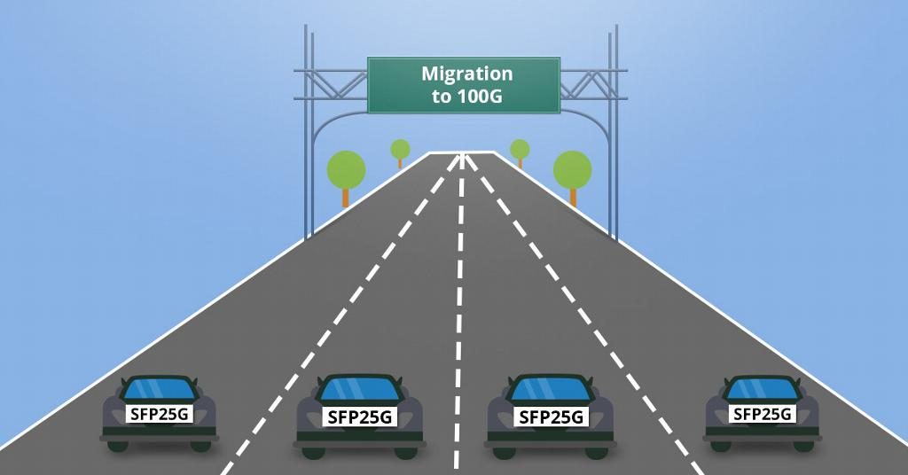
In recent years, the fast growth of data centers leads to increase in global data traffic, which give rise to the need for faster data transmission over a network. 25G Ethernet is the product of that condition. 25G Ethernet is regarded as an incremental update from 10G Ethernet, and it supports 100G Ethernet with single lane at 25Gbps. Due to the booming of 25G, some industry experts claimed that 40G Ethernet is dead, which is biased in some degree. Then 25G vs. 40G Ethernet, which is even better?

Advantages and Disadvantages of 25G and 40G Ethernet
Advantages of 25G Ethernet

Different from 40G and 100G, 25G is a single-lane variant for 25Gbps operation, and that allows a breakout of 100G, which fit the most popular form factors. Based on existing module form factors, such as SFP28 and QSFP28, 25G operations allow for a breakout connection that is configurable as either 25G per lane or the full 100G without changing the port on front of switches, bring more flexibility in the rack and front-panel connections. In addition, with the 25G Ethernet, network operators are no longer forced to use a 40G QSFP port to go from one individual device to another to achieve 100G throughput. The final advantage of 25G is that it can use existing optical plants (depending on what was installed) and increase the bandwidth by 2.5x without changing the physical infrastructure.

25g ethernet sfp28

Disadvantages of 25G Ethernet

As 25G Ethernet is just rising, the interoperability becomes an important factor to ensure wide market adoption and to offer higher speeds for future applications. Besides, compared with 10G 40G and 100G, there aren’t many products of 25G, which limit the development of 25G networks.

Advantages of 40G Ethernet

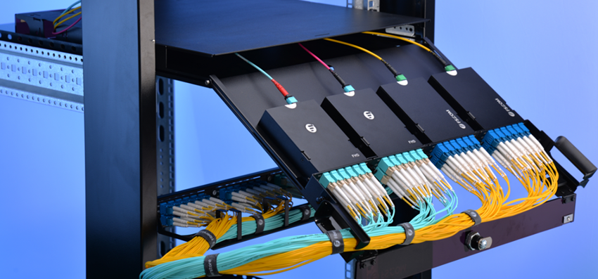
40G Ethernet is an Ethernet standard developed by the IEEE 802.3ba Task Force to support sending Ethernet frames at 40 gigabits per second. It also addresses physical layer specifications for communication across back planes, copper cabling, multimode fiber optic cable, and single mode fiber. And 40G Ethernet technology is more mature compared with 25G. In the market, there are various types of products for 40G applications, especially the MPO trunk cable assemblies, cassettes, and QSFP 40G optical modules, which offers the required bandwidth for different applications.

40G solution

Disadvantages of 40G Ethernet

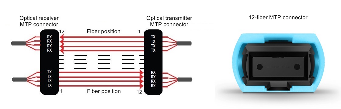
At present, 40G is popular in data centers and no drawbacks found. If we have to say one, the utilization of fibers may be one. As we all know, 12-fiber cabling solution is common in 40G networks. But there are four fibers unused, resulting in fiber waste.

Comparison Between 25G and 40G Ethernet in Network
Application

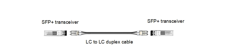
At present, 25G is mainly used for switch-to-server applications. While 40G is for switch-to-switch applications. In other words, no one is using 25G for switch-to-switch links right now. Even the industry giant like Cisco doesn’t offer 25G optical transceiver. But with the fast development of 25G Ethernet, 25G for switch-to-switch application maybe come into reality in the near future.

Switches Selection

Switches are important when comparing 25G and 40G Ethernet. Most switches are currently sold, like Cisco 93180YC-EX, Arista 7060CX-32S support both 10G and 25G, and the price is not higher than older 10G products with full backward compatibility. For example, each SFP28 port supports 1G, 10G or 25G, and each QSFP28 port supports 10G, 25G, 40G, 50G or 100G.

Cabling Options

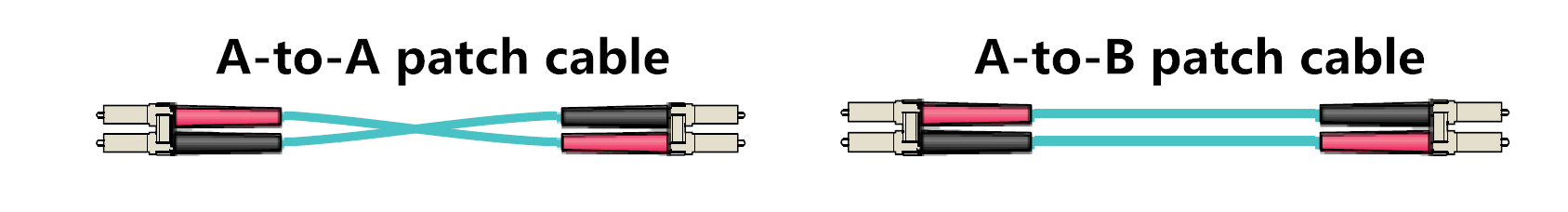
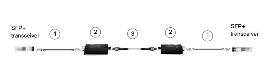
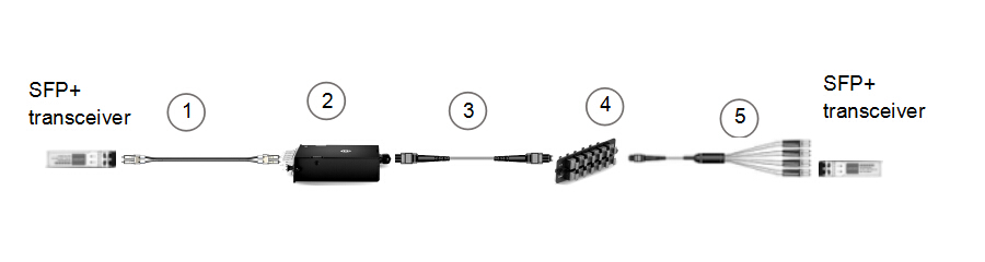
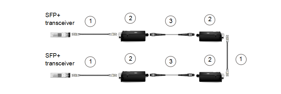
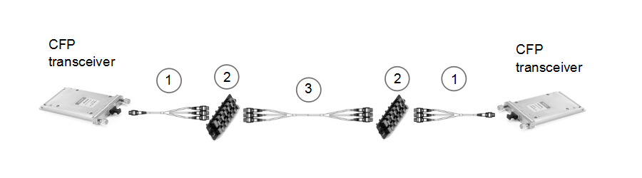
Cabling options determine how far the two types of Ethernet go. It’s a big mistake to ignore cabling. In the market, there are several types of cabling options, and there are some big swings in price. Here is a simple comparison.

25g ethernet vs 40g ethernet

Summary

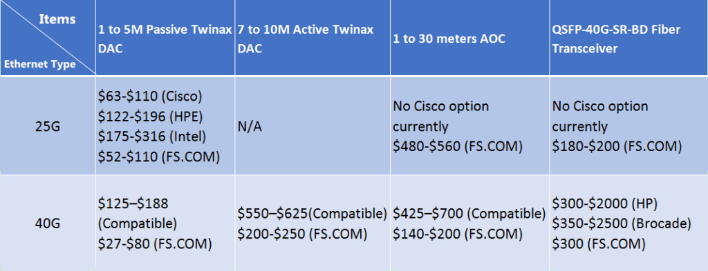
From the comparison above, we can draw a conclusion that 25G Ethernet can be used for data centers, but it doesn’t mean 40G is dead. Even though 25G Ethernet seems to have a brilliant future, under present conditions, 40G is a safe choice due to its mature market adoption. Perhaps in a few years, 25G connectivity will be a cheaper alternative.

Related articles:

Taking an In-depth Look at 25G SFP28

How Far Can 25G Ethernet Go?

25G SFP28 Cable: The Most Economical Option for ToR Server Connection

The Changing Network Architecture in 25G/100G Data Center

Connectivity Solutions for Duplex and Parallel Optics

In optical communication, duplex and parallel optical links are two of the most commonly deployed cabling structures. This post will discuss some specific connectivity solutions using 2-fiber duplex and 8-fiber/20-fiber parallel fiber optic modules.

Duplex and Parallel Optical Links

A duplex link is accomplished by using two fibers. The most commonly used connector is the duplex LC. The TIA standard defines two types of duplex fiber patch cables terminated with duplex LC connector to complete an end-to-end fiber duplex connection: A-to-A patch cable (a cross version) and A-to-B patch cable (a straight version). In this article the LC to LC duplex cables we use are all A-to-B patch cables. It means the optical signal will be transmitted on B connector and received on A connector.

two types of duplex-patch-cable

Figure 1: two types of fiber patch cables

A parallel link is accomplished by combining two or more channels. Parallel optical links can be achieved by using eight fibers (4 fibers for Tx and 4 fibers for Rx), twenty fibers (10 fibers for Tx and 10 fibers for Rx) or twenty-four fibers (12 fibers for Tx and 12 fibers for Rx). To accomplish an 8-fiber optical link, the standard cabling is a 12-fiber trunk with an MTP connector (12-fiber connector). It follows the Type B polarity scheme. The connector type and the alignment of the fibers is shown in figure 2.

8-fiber parllel system

Figure 2: parallel fiber (8-fiber) optic transmission

To accomplish a 20-fiber parallel optical link, a parallel 24-fiber MTP connector is used. Its fiber alignment and connector type is shown in figure 3.

20-fiber parallel system

Figure 3: parallel fiber (20-fiber) optic transmission
Duplex Fiber Optic Transmission Links (2-fiber to 2-fiber)

We will discuss the items required to connect two duplex transceivers in this part. These 2-fiber duplex protocols include but not limited to: 10GBASE-SR, 10GBASE-LR, 10GBASE-ER, 40GBASE-BiDi, 40GBASE-LR4, 40GBASE-LRL4, 40GBASE-UNIV, 40GBASE-FR, 100GBASE-LR4, 100GBASE-ER4, 100GBASE-CWDM4, 100GBASE-BiDi, 1GFC, 2GFC, 4GFC, 8GFC, 16GFC, 32GFC.

Duplex Direct Connectivity

When directly connecting two duplex SFP+ transceivers, an A-to-B type patch cable is required. This type of direct connectivity is suggested only to be used within a given row of racks/cabinets. Figure 4 shows two SFP+s connected by one LC to LC duplex patch cable.

2-fiber to 2-fiber direct connectivity Figure 4: 2-fiber to 2-fiber direct connectivity

Duplex Interconnect

The following figure is an interconnect for two duplex transceivers. An 8-fiber MTP trunk cable is deployed with 8-fiber MTP-LC breakout modules connected to the end of the trunk. It should be noted that the polarity has to be maintained during the transmission. And pinned connectors should be deployed with unpinned devices. Structured cabling allows for easier moves, adds, and changes (MACs). Figure 5 illustrates this solution.

2-fiber to 2-fiber interconnect (1)

Figure 5: 2-fiber to 2-fiber interconnect (1)

Item Description
1 LC to LC duplex cable (SMF/MMF)
2 MTP-8 to duplex LC breakout module (pinned)
3 8 fibers MTP trunk cable (not pinned)

Figure 6 is also an interconnect solution for SFP+ transceivers, but on the right side an 8-fiber MTP to 4 x LC harness cable and an MTP adapter panel are used instead. This solution works best when connectivity is required for high port count switch.

2-fiber to 2-fiber interconnect (2)

Figure 6: 2-fiber to 2-fiber interconnect (2)

Item Description
1 LC to LC duplex cable (SMF/MMF)
2 MTP-8 to duplex LC breakout module (pinned)
3 8 fibers MTP trunk cable (not pinned)
4 96 fibers MTP adapter panel (8 port)
5 8 fibers MTP (not pinned) to duplex 4 x LC harness cable
Duplex Cross-Connect

This solution is a duplex cross-connect. It will allow all patching to be made at the main distribution area (MDA) with maximum flexibility for port-to-port connection. Figure 7 illustrates the cross-connect solution for duplex connectivity.

2-fiber to 2-fiber cross-connect

Figure 7: 2-fiber to 2-fiber cross-connect

Item Description
1 LC to LC duplex cable (SMF/MMF)
2 MTP-8 to duplex LC breakout module (pinned)
3 8 fibers MTP trunk cable (not pinned)
Parallel Fiber Optic Transmission Links

We will discuss items required to connect two parallel (8-fiber or 20-fiber) transceivers in this part. These protocols include but not limited to: 40GBASE-SR4, 40GBASE-xSR4/cSR4/eSR4, 40GBASE-PLR4, 40GBASE-PSM4, 100GBASE-SR4, 100GBASE-eSR4, 100GBASE-PSM4, 100GBASE-SR10.

Parallel Direct Connectivity (8-fiber or 20-fiber)

When directly connecting two QSFP+ or QSFP 28 transceivers, an 8-fiber MTP trunk cable is needed. For directly connecting two CFP transceivers, a 24-fiber MTP trunk cable is needed.

8-fiber to 8-fiber direct connectivity

Figure 8: 8-fiber to 8-fiber direct connectivity
Parallel Interconnect (8/20-fiber)

Figure 9 shows an interconnect solution for two CFP modules (20-fiber). To break-out the CFPs to transmit the signal across an 8-fiber infrastructure, a 1 x 3 breakout harness (24-fiber MTP to three 8-fiber MTP) is required. To achieve an interconnect for two 8-fiber optics, we can replace the breakout harness by an 8-fiber MTP (pinned) trunk and the 24-fiber MTP trunk by an MTP (not pinned) trunk.

20-fiber to 20-fiber interconnect

Figure 9: 20-fiber to 20-fiber interconnect

Item Description
1 1×3 MTP breakout harness cable (24-fiber MTP to three 8-fiber MTP) (pinned)
2 96 fibers MTP adapter panel (8 ports)
3 24 fibers MTP trunk cable, three 8-fiber legs (not pinned)
Conclusion

This post gives brief introduction to the meaning of duplex and parallel optical link and presents some connectivity solutions for two duplex optics or two parallel optics. The corresponding items used in each solution are listed too. The transmission distance and working environment should be taken into account when applying each cabling solution. The parallel to duplex connectivity solutions will be discussed in the next post.

Functions of ONT and OLT in GPON Network

Gigabit passive optical network (GPON) is a point-to-multipoint access mechanism providing end users with the ability to consolidate multiple services onto a single fiber transport network. To realize this technology, many devices are used to support the network, such as optical splitter, ONT, OLT, etc. In this article, we will mainly discuss the functions of ONT and OLT in GPON network.

GPON

Functions of ONT and OLT

Optical network terminal (ONT) is an optical modem that connects to the termination point with an optical cable. It is used at end user’s premise to connect to the PON network on one side and interface with the user on the other side. Data received from the customer end is sent, aggregated and optimized by the ONT to the upstream OLT. ONT is also known as optical network unit (ONU). ONT is an ITU-T term, while ONU is an IEEE term. They both refer to the user side equipment in GPON network. A small difference between them might be the application locations. ONU can work in different temperature and weather conditions.

ONT

Optical line terminal (OLT) is the endpoint hardware equipment located in a central office of the PON network. Its basic function is to control the float information in optical distribution network (ODN) to go in both directions. OLT converts the standard signals used by fiber optic service (FiOS) to the frequency and framing used by PON system. In addition, it coordinates the multiplexing between the ONT conversion devices. There are two float directions for OLT system. One is the upstream direction to distribute different types of data and voice traffic from users. The other is the downstream direction which gets data, voice and video traffic from metro network or from a long-haul network and sends it to all ONT modules on the ODN.

ONT and OLT

How to Add or Delete ONT on OLT?

Way to Add ONT on OLT

If the password of an ONT is obtained, you can run the ONT add command to add the ONT offline. However, if the password is unknown, you can run the port portid ont-auto-find command in the GPON mode to enable the ONT auto-find function of the GPON port, and then run the ONT confirm command to confirm the ONT. When the ONT is added, you need to run the display ONT info command to see the current status of ONT. If the control flag is active,

Way to Delete ONT on OLT

When you need to delete the ONT on OLT, please use the delete command. Then ONT configuration data is deleted with the deletion of the ONT and the online ONT is forced offline. ONT can’t be deleted when it has been configured with other services. You need to unbind the service first before delete the ONT.

How to Troubleshoot ONT?

To troubleshoot the ONT, you should remember that the most important step is to connect your computer directly to the ONT to see if the problem goes away. You can use the Ethernet cable for connection. If the problem still exists, you can reconnect the ONT power supply to clear its internal cache. If the network can not be restored after the above methods, maybe you need to consult professionals for help.

Conclusion

ONT and OLT are indispensable components in the GPON network system. If you are considering to purchase the ONT or OLT devices, FS.COM is a good place to go. Different types of ONT and OLT equipment are provided with high integration, flexible adaption and great reliability to meet all your requirements.

Related Article:
Comparison Between EPON and GPON
ABC of PON: Understanding OLT, ONU, ONT and ODN

Guide to Build Up Home Network

Since network has been ubiquitous in today’s world, building it into our home seems to be necessary when moving into a new house. However, millions of households are haunted by the terrible network cabling mess. Cables are usually tucked into corners, tangled around the ceiling or jumbled behind devices. If you want these problems to be solved, a good plan for home network is a must. Have you ever thought about setting up a fiber optic home network via network cables all by yourself? This article can be the guide to the beginners.

home network

Advantages of Good Home Network

A good fiber optic home network is beneficial to the visual neatness. House will be more tidy when less cables are exposed to the surface. Most wires will be installed through the walls. Possibility of cable mess is greatly reduced and you don’t need to be nervous about tripping over by the cables. Constructing a good home network also increases the value of the home. If the house is for sale in the future, a built-in network can certainly raise the price potentials. In addition, when setting up the network, you can add some aesthetic designs to your house like painting the wall into a new color or moving wall plates to appropriate places.

Different Network Connections

There are generally three types of home network connections. Choosing a suitable type for the network is also important.

Ethernet/LAN

Ethernet or LAN network uses physical cables to plug into the LAN port of router or network switch. The speed for Ethernet cables can reach up to 1 Gbps. The cable length usually runs up to 100 meters without any influence to performance. Using a wired network is more secure and reliable. However, if you want to totally get rid of the cabling mess, there are better alternatives.

wired fiber optic home network

WiFi/Wireless LAN

People nowadays are familiar with this wireless network. It is the network that operates through radio waves without any wires. The latest 802.11ac standard defines the WiFi network for the maximum of gigabit speed. Wireless network allows for easier access to mobile devices and is simple to be set up. However, the signal also has a limited range and is easily interfered by other devices or buildings.

wireless network

Power Line

Power line network, known as Ethernet over Power (EoP) is carried through the existing wiring. With the help of adapter plugs, it can be connected to small devices by standard Ethernet cables. It is a good option when installing traditional network cabling is not possible but you want better performance than wireless.

Components Needed for Home Network

Central hub, Ethernet jack, wall plate and Ethernet cable are some basic components for the home network. Technically, a basic 8 port switch could accomplish your goals in the central hub. Ethernet jack makes the installation more professional and allows for easier connection with wall plate. Wall plate also provides an easier and stable location for cables to plug into. Of course, Ethernet cable is indispensable and should be selected according to your needs.

How to Expand Fiber Optic Home Network

When Ethernet ports are running out on the router, you can buy a new one to add more ports so as to expand the wired network. As for the wireless network, the problem is always about the range of signal coverage. You can try the commercial WiFi extender, or use metal can focus the antenna in a specific direction.

Conclusion

Many homes are now building up networks into their places. A wonderful fiber optic home network can provide you with better online experience. This post only offers some basic knowledge about home network. If you are unprofessional, please consult the specialists first before starting the construction.

Related Article:
Let Surveillance Camera Guard Your Home Safety
10Gb Switch for Home

Fiber Protection Sleeve Secures Your Fusion Splices

Fiber optic splicing, especially fusion splicing, has become increasingly important for OSP (outside plant) deployment. The process is by joining the two fiber ends to create longer cable runs. As we know, spliced bare fibers are fragile to be easily breakable. Therefore, a good protection for the spliced fibers during fiber optic splicing is extremely necessary. Luckily, a small component named fiber protection sleeve perfectly solves the issue. It acts as a strong coat for the fiber splices to prevent unpredictable fractures. This post will take you to understand the basic knowledge about fiber sleeve.

Construction of Fiber Sleeve

Generally speaking, a fiber sleeve consists of three parts. The first part is the inner tube made by hot-meltable adhesive. This material can encapsulate the fusion splice joint and provides vibration damping and an environmental seal so as to protect the fiber from damage and contaminants. The second part is a reinforcing strength member outside the inner tube. The strength member can be made of stainless steel, ceramic or non-metallic. It offers extra rigidity to prevent misalignment, micro bending or breakage of the fiber. The third part is the heat-shrinkable outer tube made of cross-linked polyolefin. This tube provides an instant shrink-force and drives the adhesive liner into all areas of the splice and excludes all the air. The following picture shows the structure of a fiber protection sleeve.

fiber sleeve-structure

How Does It Work?

When the optical fiber is melt during the fusion splicing, the technician will use the sleeve on the melting point as a protection. Once the hot-meltable adhesive tube touches the melted fiber, it also melts to tightly wrap the fiber joint for the filling and sealing functions. Likewise, when the heat-shrinkable tube is heated, it shrinks to wrap the fiber joint, strength member and hot-meltable tube to form a unity preventing moisture and increasing fiber joint’s strength.

Two Types of Fiber Protection Sleeve

Single Fiber Protection Sleeve

This kind of protection sleeve is used for single mode fiber. Its strength member adopts the stainless steel needles to reduce fiber damage. Typical lengths are 40 mm and 60 mm. The sleeve color is selective, but most people would choose the transparent tube for better inspection of the fiber status.

single-fiber-protection-sleeve

Ribbon Fiber Protection Sleeve

The ribbon type is to protect ribbon splices of multiple fiber counts. The ceramic strength member is used to supporting the splices. Fiber counts in a ribbon sleeve vary from 2 to 12 fibers. The length of the sleeve is usually 40 mm. If stronger protection is required, you can choose the ribbon protection sleeves with double ceramic strength members.

ribbon-fiber-protection-sleeve

Be Aware of These Precautions

While utilizing the fiber protection sleeves, there are some important precautions for operators to know. The benefits of the precautions are about avoiding unnecessary loss and securing the fiber for a long-term use.

  • Point 1, do not leave air bubbles in the protection tube. This ensures the long-term reliability of the fiber splices.
  • Point 2, the tension applied to the fiber should be uniform so that the fiber can stay straight in the protective sleeve.
  • Point 3, the tension applied to the fiber should not be too large in case fiber cracks increase.
  • Point 4, try to avoid fiber twisting. Because this may cause micro-bending and unnecessary fiber loss.
  • Point 5, do not release the tension until the heat-shrinkable tube is completely shrunk, cooled and shaped. This can avoid uneven heating which leads to fiber bending.

Conclusion

Fiber optic protection sleeve is usually used during the process of fiber optic splicing. Although the fiber sleeve is very small, it provides great support for the fiber joint. Single fiber protection sleeve and ribbon fiber protection sleeve are two common types in the market. All the above are available in FS.COM. If you are interested, please visit the website for more information.

Related Articles:
How To Repair the Accidentally Cut Fiber Optic Cable?
Fiber Optic Pigtail: What Is It and How to Splice It?