MTP-8: Simplest Way to Get 40G Connection

As data centers networks are shifting from 10G to 40G and beyond, it is necessary to seek ideal ways to connect 40G high speed switches populated with higher rate transceivers QSFP+, and to connect 40G switch to existing 10G elements populated with SFP+ modules. There are different approaches to connect 40G switches, or to connect 40G switch to 10G switch. However, by using MTP-8 solution, the simplest way to achieve direct 40G connectivity has been proved feasible and favorable in real applications. This article will introduce the deployment of MTP trunk cable in 40G to 40G connection, and MTP harness cable in 10G to 40G connection.

Basis of MTP Trunk and Harness Cable

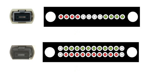
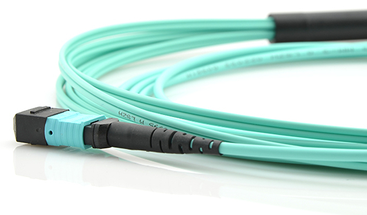
MTP trunk cable has MTP connectors terminated on both ends of the fiber optic cable. It is often used to connect MTP port modules for high density backbone cabling in data centers and other high dense degree environments. Currently, most of the MTP trunk cables for high data rate like 40G and 100G are still 12-fiber or 24-fiber. MTP harness cable, also called MTP breakout or fan-out cable, has MTP connectors on one end and discrete connectors (duplex LC, SC, etc.) on the other end. The most common configurations of MTP-LC harness cables are 8-fiber MTP to 4 LC duplex, 12-fiber MTP to 6 LC duplex and 24-fiber MTP to 12 LC duplex. A single MTP connector is able to terminate the combination of 4, 8, 12, 24, 48 fiber ribbon cables. The multi-fiber design provides quick deployment and scalable solution that improves reliability and reduces installation or reconfiguration time and cost.

10G to 40G Connection via MTP Harness Cable

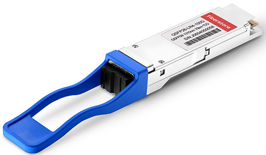
In order easily and quickly finish the migration from 10G network to 40G network, you can use 8-fiber MTP to 4 LC duplex harness cable, 40GBASE-SR4 QSFP+ and 10GBASE-SR SFP+ modules. The configuration of such a link is illustrated by figure 1. On the left the 8-fiber MTP connector is plugged into the MTP port of the 40GBASE-SR4 QSFP+ transceiver installed on the 40G switch; on the right side four duplex LC connectors are plugged into the ports of four 10GBASE-SR SFP+ transceivers installed on the 10G switch. In 10G to 40G migration, using 8-fiber MTP to LC harness cable can ensure every strand of fiber be used, and no one wasted.

10G to 40G via MTP-8 harness

Figure 1: 10G to 40G Migration via MTP-LC Harness Cable

40G to 40G Connection via MTP Trunk Cable

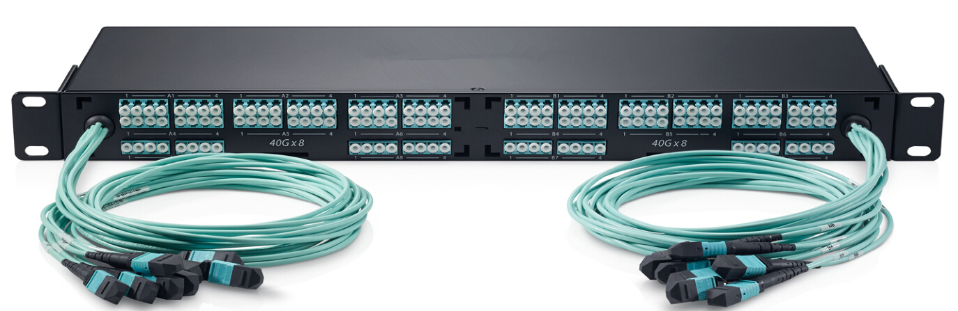
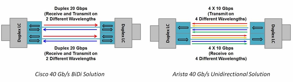
To support your 40G networking needs, you can simply use 12-fiber MTP trunk cable and 40GBASE-SR4 QSFP+ transceiver to accomplish a quick connection for two 40G switches in your network. The following figure shows a concrete example which uses one 12-fiber MTP trunk cable and two 40GBASE-SR4 QSFP+ transceivers to connect two 40G switches. Though the MTP trunk cable in this case is base-12, the fiber count actually in use is eight, leaving four strands unused. That is to say delivering 40G over 4 lanes multimode fiber at 10 Gb/s per lane. Totally only eight fibers (4 transmit, 4 receive) are required for the 4x10G solution. It is the same as the 4x25G solution for 100G.

40G connection via MTP-8 trunk

Figure 2: 40G to 40G Connection via MTP Trunk Cable

The above two examples are both applications of MTP-8 solution in 40G connectivity. You will find that only a few components are needed in the whole installation, and the link will be very easy and flexible, as well as cost-effective.

Conclusion

Current 40G connectivity can be obtained by MTP-8 solution. Though present market is still popular with 12-fiber or 24-fiber MTP, 8-fiber MTP solutions that are starting to hit the market are considered the most efficient option since they support current and future duplex fiber applications (such as 200G and 400G) and using modules that break out 8-fiber MTPs to duplex LCs, as well as current and future 8-fiber applications without the need for conversion cords or modules.

Preparing MTP/MPO System for Different Applications

There is no doubt that 40G and 100G networks become the trend in today’s cyberspace. Many applications are pursuing the high bandwidth throughput, therefore using high-density patching is inevitable. But is there any good solution for high-density structured cabling? Definitely, MTP/MPO system solves your trouble with a wide range of MTP/MPO assemblies. It is a technique enabling multi-fiber connections to be used for data transmission. The high fiber count creates the endless possibilities of high-density patching. The easy installation of MTP/MPO assemblies also saves lots of operating time. This article will introduce some regular MTP/MPO products and their common applications.

Common MTP/MPO Products

To accommodate the needs for high speed networks, MTP/MPO system has many optics to fit for different applications. There are usually MTP/MPO cables, MTP/MPO cassettes, MTP/MPO optical adapter and MTP/MPO adapter panels.

MTP/MPO cables are terminated with MTP/MPO connectors at one end or both ends. The fiber types are often OM3 or OM4 multimode optical fibers. MTP/MPO cables has three basic branches of trunk cables, harness/breakout cables and pigtail cables. MTP/MPO trunks can be made with 8, 12, 24, 36, 48, 72 or even 144 fibers for single-mode and multimode applications. MTP/MPO harness cables are usually terminated with a MTP/MPO connector at one end and different connectors, such as LC, SC, ST connectors, etc. at the other end. Pigtails only have one end terminated with a MTP/MPO connector, and the other end is used for fiber optic splicing with no termination.

mtp-mpo-cables

As for the MTP/MPO cassettes, they are equipped with standard MTP/MPO connectors to be deployed in an ODF (optical distribution frame) for high-density MDA (main distribution area) and EDA (equipment distribution area) in data centers.

mtp-mpo-cassette

Other components like the black-colored MTP/MPO optical adapter and adapter panels build the connection between MTP/MPO cable to cable or cable to equipment.

mtp-mpo-optcial-adapter-and-adapter-panels

Applications
Data Center SAN (Storage Area Network)

MTP/MPO plug and play modules have been widely used in data centers, such as backbone products supporting hundreds of optical ports. Therefore, single cabinets must hold quantities of optical interconnections and patch cords. Since SAN needs high-density and modular cabling for easy reconfiguration, MTP/MPO plug and play modules are perfect to meet the requirements of these infrastructures.

data-centre-san

Data Center Co-Location

Co-location data centers require flexibility of network expansions for new customers or new services. The pre-terminated UHD (ultra high density) MTP/MPO system is ideal for fast and rapid deployment or expansions in these networks.

data-centre-co-location

Enterprise/Campus

UHD system modules can be installed in enterprise or campus networks using “plug and play” MTP/MPO or “just play” pre-terminated modules. Installation is fast and easy, which requires no professional fiber optics knowledge. Traditional splicing installation techniques can also be applied. There is a wide selection of cable types including tight buffer, loose tube, micro cable, etc. for employment.

enterprise-campus

Telecom Central Office

UHD system is a small footprint and is perfect for reduced space in high-density rack environments. Modules can be pre-terminated or feature MTP/MPO ports for improved reconfiguration. In addition, they can be fitted with splice management for traditional installation techniques.

telecom-central-office

Summary

In a word, MTP/MPO system is a perfect solution suited for high-density applications. The MTP/MPO products are designed to be space-saving and easy to manage. Initial investment for MTP/MPO assemblies might be expensive, but it is a wise and cost-effective decision to deploy the system for your application in the long run.

100G Optical Transceiver Solutions

Network has been rapidly developed over the years. People are always dreaming of entering into the world of higher bandwidth. And now the dream has come true since we already reach the 100 gigabit Ethernet (100 GbE) networking. This technology enables the transmission at rates of 100 gigabits per second (100 Gbit/s). The standard was first defined by the IEEE 802.3ba in 2010. To accommodate the trend, different types of 100G optical transceiver emerge as a reflection of the development. QSFP28 (quad small form-factor pluggable 28), CFP (centum form-factor pluggable) and CXP (centum extended-capability form-factor pluggable) are most commonly used optical transceiver solutions for 100G active equipment. Today, the article will mainly introduce these three solutions.

100G Optical Transceiver Solutions
CFP

Specified by a multi-source agreement (MSA) between competing manufacturers, CFP was designed to replace many former transceivers like SFP+, SFP, XFP with a significantly larger support of 100 Gbps. The electrical connection of a CFP uses 10 x 10Gbps lanes in each direction (RX, TX). The optical connection can support both 10 x 10Gbps and 4 x 25Gbps variants. In addition, there are another two CFP next-generation 100G form factors — CFP2 and CFP4. Compared to the existing CFP, CFP2 and CFP4 are respectively double and quadruple front panel port density. All of them are now available on the market.

CFP

QSFP28

QSFP28 transceiver is designed for 100G Ethernet which uses the 4 x 25 wiring specification. It has the same size as 40G QSFP+ but with a higher performance. The 100G QSFP28 is implemented with four 25Gbps lanes. “28” stands for the highest possible rate of 4x28Gbps in transmission. Two basic versions of QSFP28 transceivers are 100GBASE-SR4 QSFP28 transceiver and 100GBASE-LR4 QSFP28 transceiver, which are respectively used for multimode fiber (MMF) and single-mode fiber (SMF) 100G applications. 100GBASE-SR4 QSFP28 operates at multimode fiber for a distance of 100 m. 100GBASE-LR4 QSFP28 can support a much longer distance of 10 km.

qsfp28
100GBASE-LR4 QSFP28
CXP

As a complement to CFP, CXP is also specified by MSA aiming at the clustering and high-speed computing markets. CXP has a higher density network interface with 45 mm in length and 27 mm in width, making it slightly larger than an XFP or 1/4 size of a CFP transceiver. It has a form-factor pluggable active device interface with 12 transmit and 12 receive lanes, capable of supporting bit-rates in excess of 10 Gbps per lane on a variety of optical transmission technologies.

cxp

Future Trend of Optical Transceivers in Data Centers

In the future, higher bit rates over 100G are the inevitable trend in data centers. The next data center developments will be following the 4x trend set by 40G and 100G, such as 200G, 400G, etc. Accordingly, optical transceivers should keep up with the steps and satisfy higher demands.

In 200G applications, next generation switching ASICs (Application Specific Integrated Circuits) are expected to have native port speeds of 50G and 128 ports, which correspond to a net throughput of 6.4 Tbps. This means that 200G QSFP modules (QSFP56, 4 x 50 Gbps) would result in a front panel bandwidth of 6.4 Tbps (32 x 200 Gbps).

For 400G applications, the module must accommodate either 16 x 25G or 8 x 50G electrical input lanes, which exceeds the 4 lanes defined for the QSFP. 400G transceivers will have larger size than QSFP. However, meeting the 3.5W power limit of QSFP modules appears infeasible for some 400G implementations. Thus, proposals for larger form factors for 400G can be anticipated from CFP MSA, which has had large success in 100G with CFP, CFP2, and CFP4. In this case, a key requirement will be that the size allows for at least 16 ports on the front panel in order to satisfy a net throughput of 6.4 Tbps (16 x 400 Gbps, and possibly more).

Conclusion

The market of 100G optical transceivers is accelerating. It is no doubt that more 100G transceivers and other assemblies will be deployed in data centers. QSFP28, CFP series and CXP are presently the most suitable solutions for 100G applications. Definitely one of them can solve your project needs.

40G Solutions: Duplex Fiber or MPO/MTP Fiber?

There’s been a lot of talk lately surrounding bidirectional 40 Gb/s duplex applications, or BiDi for short. Currently offered as a solution by Cisco®, BiDi runs over duplex OM3 or OM4 multimode fiber using QSFP modules and wavelength division multiplexing (WDM) technology. It features two 20 Gb/s channels, each transmitting and receiving simultaneously over two wavelengths on a single fiber strand – one direction transmitting in the 832 to 868 nanometer (nm) wavelength range and the other receiving in the 882 to 918 nm wavelength range. Avago Technologies also offers a similar QSFP BiDi transceiver.

Unidirectional 40 Gb/s duplex fiber solutions are available from Arista and Juniper. These differ from the BiDi solution in that they combine four 10 Gb/s channels at different wavelengths – 1270, 1290, 1310, and 1330 nm – over a duplex LC connector using OM3 or OM4 multimode or singlemode fiber. These unidirectional solutions are not interoperable with BiDi solutions because they use different WDM technology and operate within different wavelength ranges.

40G Solutions

While some of the transceivers used with these 40 Gb/s duplex fiber solutions are compliant with QSFP specifications and based on the IEEE 40GBASE- LR4 standard, there are currently no existing industry standards for 40 Gb/s duplex fiber applications using multiple wavelengths over multimode fiber – either bidirectional or unidirectional. There are standards-based 40 Gb/s applications over duplex singlemode fiber using WDM technology, but standards-based 40 Gb/s and 100 Gb/s applications over multimode use multi-fiber MPO/MTP connectors and parallel optics (40GBASE-SR4 and 100GBASE-SR4).

40 Gb/s duplex fiber solutions are promoted as offering reduced cost and installation time for quick migration to 40 Gb/s applications due to the ability to reuse the existing duplex 10 Gb/s fiber infrastructure for 40 Gb/s without having to implement MPO/MTP solutions. However, some of the concerns surrounding these non-standards based 40 Gb/s duplex fiber solutions include:

  • Lack of standards compliance and lack of interoperability with standards-based fiber solutions
  • Risk of being locked into a sole-sourced/proprietary solution that may have limited future support
  • BiDi and other 40 Gb/s duplex transceivers require significantly more power than standards-based solutions
  • Lack of application assurance due to operation outside of the optimal OM3/OM4 wavelength of 850 nm
  • Limited operating temperature range compared to standards-based solutions

Due to the aforementioned risks and limitations of using non-standards-based 40 Gb/s duplex fiber solutions, we recommends following industry standards and deploying 40GBASE-SR4 for 40 Gb/s applications today. While this standard requires multiple fibers using an MPO/MTP-based solution, it offers complete application assurance and interoperability, as well as overall lower power consumption.

Furthermore, TIA and IEC standards development is currently underway for wideband multimode fiber (WBMMF), which is expected to result in a new fiber type (potentially OM5 or OM4WB) that expands the capacity of multimode fiber over a wider range of wavelengths to support WDM technology. While not set in stone, the wavelengths being discussed within TIA working groups are 850, 880, 910, and 940 nm.

Unlike current 40 Gb/s duplex fiber applications, WBMMF will be a standards-based, interoperable technology that will be backwards compatible with existing OM4 fiber applications. WBMMF is expected to support unidirectional duplex 100 Gb/s fiber links using 25 Gb/s channels on 4 different wavelengths. WBMMF will also support 400 Gb/s using 25 Gb/s channels on 4 different wavelengths over 8 fibers, enabling existing MPO/MTP connectivity to be leveraged for seamless migration from current standards-based 40 Gb/s and 100 Gb/s applications to future standards-based 400 Gb/s applications.

Differences Between 12-fiber and 24-fiber MTP/MPO Connectivity

24-fiber MTPSince IEEE 802.3ba 40GBASE-SR4 and 100GBASE-SR10 were ratified in 2010, many have looked to 24-fiber connectivity as the ideal migration solution in the data center. Using 24-fiber cabling throughout an entire channel provides extra flexibility, as users can easily migrate from 10G to 40G or 100G by simply swapping out the connectivity at the end of the channel. Pre-terminated cabling using 24-fiber connectors provides double the density of 12-fiber cabling in the same footprint, reducing the cabling required, allowing for fewer cable pathways, and improving airflow in data centers. With the growth of 24-fiber MPO/MTP solutions, some confusion and misinformation has emerged within industry circles. Especially, the differences between 12-fiber and 24-fiber MTP/MPO connectivity.

24-Fiber MTP/MPO Connectivity Is More Suitable for 100G than 12-Fiber

The current IEEE 802.3ba 100GBASE-SR10 standard defines 100GbE using 10 lanes of multimode fiber at 10 Gb/s. Progress has indeed been made in delivering 100 GbE over fewer lanes, and the IEEE 802.3bm task force is developing a new standard that would use 4 lanes of multimode fiber at 25 Gb/s per lane. This 4×25 solution would only require 8 fibers (4 transmit, 4 receive) — the same as the current 40GBASE-SR4. That means a 12-fiber MPO/MTP connector can support a single 100G channel. However, a 12-fiber connector for an 8-fiber channel is inefficient, as 4 strands in the 12-fiber connector are not used. Alternatively, by using a 24-fiber MTP connector in the horizontal cabling, it can then be converted into three 8-fiber 100G channels that run over one cable, with all 24 fibers used to support traffic.

12-fiber and 24-fiber MTPMPO

Let’s look at another example. Say you need to support twelve 100GbE channels using the next gen 4×25 Gb/s standard. With the 12-fiber MPO/MTP connectors, you would need to install 12 connectors, or 144 fibers total, with 33% of the fiber wasted. However, when supporting the same 12 channels with 24-fiber connectors, only 4 cables would be required, using 96 fibers total, at 100% fiber utilization. The 24-fiber MPO/MTP channel solution allows the use of the ratified 100GBASE-SR10 20-fiber technology today, while at the same time maximizing the installed infrastructure investment in the event of 4×25 Gb/s ratification and ultimate implementation. Choosing a 12-fiber connector strategy simply does not accomplish this. It drives down return on investment and subsequently increases the total cost of ownership. This is the exact opposite of the design intent of a data center infrastructure system.

24-Fiber Connectors Have Less Insertion Loss Than 12-Fiber Connectors

Insertion loss is a critical performance parameter in data center cabling deployments. Lower overall optical loss allows more margin for the network to operate, or in the case for some users, offers the option of more connections for patching locations. The IEEE 802.3ba 40/100GbE standard specifies OM3 fiber to a 100-meter distance with a 1.5 dB total connector loss budget. OM4 fiber for 40/100GbE is specified to a 150-meter distance with a 1.0 dB total connector loss budget. As total connector loss increates, the supportable distance at that data rate decreases. However, with the current trend of moving to distributed access/aggregation data center switch strategies such as Top of Rack (ToR), the prevalence of backbone lengths exceeding 100 meters is dramatically decreasing.

Some have mistakenly claimed that higher fiber count leads to higher loss, and one cable vendor pointed to a “typical” loss of 0.5 dB for 24-fiber connectors as evidence. In fact, the industry standard product rating for MPO/MTP connector performance of both 12-fiber and 24-fiber is 0.5 dB maximum. When using proper polishing techniques, 24-fiber MPO/MTP terminations can meet the same performance levels as 12-fiber assemblies. Improved performance can be achieved using low-loss ferrules for both 12-fiber and 24-fiber MPO/MTP connectors rated at 0.35 dB maximum.

Conclusion

As explained above, the ability to achieve the same performance in both 12-fiber and 24-fiber MPO/MTP assemblies, coupled with the clear migration advantages of using 24-fiber based components, creates a compelling argument for making 24-fiber MTP the connector of choice. We also understand that many aspects of data centers are unique to each client, designed around not just “cable and connectors”, but also inclusive of variables such as facility purpose and administrative styles. Any vendor is well advised to listen to the client and view this complex environment as a total ecosystem—inclusive of many external drivers. This is why Fiberstore also offers a full end-to-end 12-fiber MTP solutions alongside our 24-fiber end-to-end solution. We believe that providing options to our clients is paramount to meeting their unique needs.