PAM4 for 100G and 400G Applications

Hyper-scale data centers have been seeking for transceiver solutions with higher port densities and lower cost per bit, which has driven the development of PAM4 (Four-Level Pulse Amplitude Modulation) technology. Compared to the expensive multi-state coherent modulation scheme, simple PAM4 can deliver the right combination of speed, low cost, and low power consumption in data centers. This article is intended to introduce PAM4 for 100G and 400G applications.

What Is PAM4?

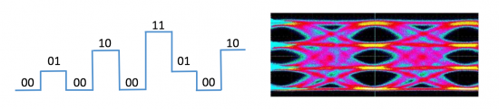
PAM4 is a technology that uses four different signal levels for signal transmission and each symbol period represents 2 bits of logic information (0, 1, 2, 3). By transmitting two bits in one symbol slot, PAM4 halves the signal bandwidth. With half of the bandwidth, PAM4 can achieve 50Gb/s data rate transmission in the 25Gb/s electrical tolerance environment. Also, PAM4 can minimize signal degradation and double the data rate. PAM4 allows us to put more data onto the existing fiber. In other words, if you want to increase bandwidth, you don’t have to reconfigure the data center with more fibers, just using advanced modulation PAM4 technology to increase the data rate. These components for single-lambda 100G can be extended to 400Gbps transceivers with four-channel drivers and CWDM4 wavelengths. However, these advanced modulation techniques impose additional requirements on the optical components used, especially consume higher amounts of electrical power.

alt What Is PAM4?

PAM4 or CWDM4 for 100G and 400G Applications

Although speed is important in the data center, economics and special constraints make cost and complexity more important than speed. Most of the data centers have already worked toward 100G, 200G, and even 400G with the technology of PAM4 and CWDM4, so which is the best for 100G and 400G application?

PAM4 for 100G and 400G Applications

PAM4 is considered to be a cost-effective and efficient alternative solution for 100G and 400G construction. For 100G transceiver modules, single-wavelength PAM4 technology reduces the number of lasers to one and eliminates the need for optical multiplexing. For 400G, the largest cost is expected to be optical components and related RF packages. PAM4 technology uses four different signal levels for signal transmission. It can transmit two bits of logic information per clock cycle and double the transmission bandwidth, thus effectively reducing transmission costs. This effectively solves the problem of high cost while meeting bandwidth improvements.

CWDM4 for 100G and 400G Applications

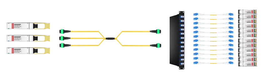
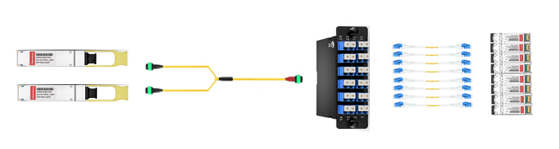
CWDM4 (Coarse Wavelength Division Multiplexing) technology is another cost-effective solution for large-scale deployment and migration in data centers. For 100G and 400G networks, the network architecture uses four lanes of 25 Gb/s, using CWDM technology to transport 100G and 400G optical traffic on duplex single mode fiber (SMF). WDM reduces the number of fibers required to achieve this type of transmission, ultimately reducing the cost of the entire board.

Conclusion

As a popular signal transmission technology for high-speed signal interconnection in next-generation data centers, PAM4 signals are widely used for electrical and optical signal transmission on 100G, 200G, and 400G interfaces. There are also a large number of PAM4 QSFP28 and PAM4 SFP28 modules available on the market to help you build your network.

Related Articles:
Global Optical Transceiver Market: Striding to 200G and 400G
Decoding 100G QSFP28 Transceiver

FS N5850-48S6Q vs QuantaMesh BMS T3048-LY8 10Gb Bare Metal Switch

As vendors continue to tout networking architectures that decouple software from hardware, bare metal switches are moving into the spotlight. Built on merchant silicon, these network switches offer fewer features than proprietary chips but provide a lower cost and more flexible switching alternative. It also allows network administrators to quickly respond to changing business needs at lower capital costs and reduce the complexity of network operations. In this article, we will introduce FS N5850-48S6Q 10Gb bare metal switch and QuantaMesh BMS T3048-LY8 10Gb bare metal switch and compare them for your reference.

What Is FS N5850-48S6Q?

FS N5850-48S6Q switch is a top-of-rack (TOR) or leaf 10Gb bare metal switch in a compact 1U form factor, ideally suited for high performance and programmable data center environments. FS N5850-48S6Q provides 48 SFP+ 10Gb ports and 6 QSFP+ 40Gb ports, and each 40Gb port can be configured as 4x10Gb up to a total system limit of 72 10Gb ports. It performs excellent low latency and power efficiency in a PHY less design while providing high-reliability features such as redundant and hot-swappable power supplies and fans in forward and reverse airflow configurations. The switch supports advanced features such as MLAG, VxLAN, SFLOW, SNMP, MPLS etc, making it ideal for traditional or fully virtualized data centers. FS N5850-48S6Q 10gbe switch supports current and future data center requirements, including an x86-based control plane for easier integration of automation tools, an ONIE installer for 3rd party network operating systems and compatibility with Software Defined Networks via OpenFlow 1.3.11. Additionally, FS N5850-48S6Q supports the advanced hardware-based VXLAN feature to support over 16M virtual networks.

altFS N5850-48S6Q vs QuantaMesh BMS T3048-LY8 10Gb Bare Metal Switch

What Is QuantaMesh BMS T3048-LY8?

QuantaMesh T3048-LY8 switch is a 10Gb bare metal switch in a compact 1U form factor for higher performance, increased availability, lower latency, and better serviceability. It supports 48 SFP+ (1/10GbE speed) and 6 QSFP+ (10/40GbE speed) ports. By leveraging the new generation merchant silicon chips, QuantaMesh T3048-LY8 is a high-performance, high-density Ethernet switch, which is affordable and can be used to deploy data center infrastructure. By preloading the ONIE (Open Network Installation Environment), QuantaMesh BMS T3048-LY8 provides flexibility and allows choice of network operating system supported by ONIE installer. The CPU board design allows QuantaMesh BMS T3048-LY8 to install different CPUs in order to meet software requirements. This provides an agile installation process and faster response for the changing business demands.

altFS N5850-48S6Q vs QuantaMesh BMS T3048-LY8 10Gb Bare Metal Switch

FS vs QuantaMesh 10Gb Bare Metal Switch

Based on the above information, we have formed a general cognition of FS and QuantaMesh 10Gb bare metal switches. we learn that the two switches have similar functions and structures, but their performances are different. What are the differences? Let’s look at the chart below.

Names FS N5850-48S6Q QuantaMesh BMS T3048-LY8
Ports 48 48
Switch Chip Trident 2 BCM56854 Broadcom StrataXGS Trident2
Switching Capacity 1.44Tbps Full-duplex 1440Gbps
CPU Intel Rangeley C2538 2.4Ghz 4-core Intel Atom Processors
Forwarding Rate 1 Bpps 1071Mpps
Latency 680ns <600ns
Flash Storage Memory 16GB SSD 8GB Micro SD
Jumbo frame 9K Bytes 12K Bytes
Airflow Design Back-to-Front Both Directions
Compatible Software Option Cumulus Linux, ICOS, Open Network Linux, PicOS Cumulus Linux, Open Network Linux, QNOS, OF-DPA

Which One Is Better for You?

As can be seen from the above comparison, FS N5850-48S6Q and QuantaMesh BMS T3048-LY8 both perform well in high performance and programmable data center environments. If you want to choose between them, there are other conditions you can think about. In terms of price, QuantaMesh BMS T3048-LY8 is priced at US$5,700, whereas FS N5850-48S6Q has a more attractive price of $2,999. If your budget is tight, FS N5850-48S6Q 10Gb bare metal switch may be a good choice for you. Another concern for consumers is the warranty. As we all know, high-quality products usually provide excellent after-sales service to enhance their reputation. For both products, QuantaMesh only offers a three-year lifetime warranty, while FS offers a five-year lifetime warranty. In contrast, FS seems to be more concerned about the rights of consumers. Therefore, if you want a cost-effective 10Gb bare metal switch with better service, FS N5850-48S6Q 10Gb bare metal switch will be your best choice.

Conclusion

FS N5850-48S6Q 10Gb bare metal switch belongs to FS N-Series switches and is designed for next-generation metro, data center and enterprise network applications. Apart from that, FS also provides a variety of port switches such as 32 port switch, 48 port switch etc. just for your needs. If you would like to bring a bare metal switch to your network, contact us at FS.COM.

Related Articles:
FS N8500-48B6C vs Edgecore AS7312-54XS 25G Bare Metal Switch
32 Port 40G Switch: With Broadcom ICOS or ONIE?

Compatible Optical Modules For FS S5850-48S2Q4C 100G Switch

With the development of advanced technology, 100G products is fast growing in 100G market to cater to the demand of a higher bandwidth. How about 100G switches? Recently, FS launches S5850/S8050 series 100G switches including two configurations: S5850-48S2Q4C and S8050-20Q4C, to meet the market demands. The FS S5850-48S2Q4C switch is high performance and cost-effective Ethernet access and aggregation platform to enterprise, data center and metro application. This article aims at providing a detailed information about FS S5850-48S2Q4C 100G switch and its compatible optical modules.

Features of FS S5850-48S2Q4C Switch

The FS 100G switch S5850-48S2Q4C is designed based on the fourth generation high-end scalable chipset, which supports L2/L3/Data Center/Metro features. In a compact 1 RU form factor, the 100G switches can provide line-rate L2 and L3 switching across up to 48 SFP+ ports or 20 QSFP+ ports, and offer 2× 40GbE QSFP+ or 4×100GbE QSFP28 uplink connections. Compared to other 100G switch products on the market, this 100G switch have the following characteristics:

  • Data center lever hardware design.
  • Design for traffic visual and trouble-shooting.
  • Design for data center applications.
  • Focusing on supporting 40G/100G ports with large capacity and high density port.
  • Complete system software with comprehensive protocols and applications to facilitate rapid service deployment and management for both traditional L2/L3 networks and Data Center networks.

S5850-48S2Q4C-100G-switches

Compatible Optic Modules For S5850-48S2Q4C

The FS 100G switch S5850-48S2Q4C supports a full rang of 10, 40 and 100 Gigabit Ethernet connectivity options. Those 10G/40G/100G ports support installation of SFP+, QSFP+ and QSFP28 transceiver modules. FS provides many high-quality compatible SFP+, QSFP+ and QSFP28 modules for S5850-48S2Q4C 100G switch.

10G SFP+ Modules

10G SFP+ modules for FS S5850-48S2Q4C

Among all the 10GBASE SFP modules on the market, 10GBASE SR SFP and 10GBASE-LR are warmly welcomed by many Ethernet users right now. The maximum transmission distance of Cisco 10GBASE-SR module can be up to 300 m and 400 m respectively on this switch by using multimode fiber OM3 and OM4. The Cisco 10GBASE-LR module can arrive a link length of 10 km on standard single-mode fiber through this switch. The 10G SFP+ modules here totally conform to the specification of this S5850-48S2Q4C 100G switch. You can select a proper one to connect.

40G QSFP+ Modules

40G QSFP+ modules for FS S5850-48S2Q4C

As we can see from the above figure, there are many 40G QSFP+ modules available to this switch. By using Cisco 40GBASE-SR4 QSFP modules, link lengths on this switch can arrive 100 m and 150 m, respectively, on laser-optimized OM3 and OM4 multimode fibers. It primarily enables high-bandwidth 40G optical links over 12-fiber parallel fiber terminated with MPO/MTP multifiber female connector. All of FS.COM’s transceivers are tested for 100% functionality and guaranteed compatible for outstanding network performance. So does the above 40G transceivers, they are completely applicable to this S5850-48S2Q4C 100G switch. Recently, there is a big slump in Cisco 40GBASE-SR4 QSFP at FS.COM. So buying Cisco 40GBASE-SR4 QSFP now is really a good deal, for it only needs $49, which can help you save a lot.

100G QSFP28 Modules

100G QSFP28 modules for FS S5850-48S2Q4C

100G QSFP28 SR4 is highly favored by many Ethernet users to connect switch. The 100G QSFP28 SR4 offers 4 independent transmit and receive channels, each capable of 25Gb/s operation for an aggregate data rate of 100Gb/s, which can be up to 100 m on this S5850-48S2Q4C 100G switch by using OM4 multimode fiber. It provides increased port density and total system cost savings. An optical fiber ribbon cable with an MTP/MPO connector can be plugged into the QSFP28 module receptacle. The compatibility of the above 100G QSFP28 modules are guaranteed, you can rest assured to use them for connecting with this S5850-48S2Q4C 100G switch. Just like 40GBASE-SR4 QSFP, Cisco 100G QSFP28 SR4 is on a big sale recently at FS.COM as well. A Cisco 100G QSFP28 SR4 is yours only by paying $269.

Summary

FS S5850-48S2Q4C switch is high performance 100G switch, offering cost-effective solutions for next generation metro, data center and enterprise Ethernet network applications. It supports 10G, 40G and 100G Ethernet network connectivity.

Interconnect Solutions for Arista QSFP-40G-PLRL4 and SFP-10G-LR

Usually for single-mode fiber optic transceivers, the interface will be designed as LC duplex type. And for these optical modules, it will be easy to achieve structured cabling by using single-mode LC duplex infrastructure. But for 40G QSFP+, some single-mode transceivers do not follow this common rule. For example, 40GBASE-PLRL4 is a single-mode module supporting a transmission distance up to 1 km, but it has to be connected with an MTP/MPO-12 UPC connector. When migrating from 10G to 40G network using 40GBASE-PLRL4 modules, both single-mode LC duplex cable and single-mode MTP/MPO cable will be used. This article will take Arista QSFP-40G-PLRL4 and SFP-10G-LR optical modules as examples to explain several interconnect solutions for them.

Specifications of Arista QSFP-40G-PLRL4 and SFP-10G-LR

Arista 40GBASE-PLRL4 QSFP+ module is designed with a single-mode parallel MTP/MPO port. It can support a maximum link distance of 1 km on single-mode fiber operating at 1310nm wavelength. Arista 10GBASE-LR SFP+ module also has a single-mode port but its interface is LC duplex type. This SFP-10G-LR transceiver supports a long transmission distance up to 10 km over single-mode fiber operating at 1310 nm. Both of them support digital and optical monitoring.

Interconnect Solutions for Arista QSFP-40G-PLRL4 and SFP-10G-LR

In the first solution, a breakout cassette is used to move one 40G signal to four individual 10G signals. A 40G MPO cable is used on the QSFP-40G-PLRL4 side and four LC uniboot cables are connected to four SFP+s. The MTP/MPO equipment we used in this solution and the solutions below are all aligned as polarity B type.

interconnect for single-mode QSFP+ and SFP+ with MPO-12 to LC cassette

Figure 1: interconnect for single-mode QSFP+ and SFP+ with MPO-12 to LC cassette.

The second connection is a very cost-effective solution for three QSFP-40G-PLRL4 to twelve SFP-10G-LR modules. Here the three breakout cables on the left are female MPO to 4xLC 8 fibers harness. Then by using two 6 LC duplex adapter panel, the three groups of 40G signals are divided into two groups that each has six 10G network devices. In this link, no fiber or port is wasted. Besides, it also allows flexible location of the QSFP+ modules, like in different chassis. By using customized bend insensitive single-mode LC duplex fiber patch cable, high performance transmission at longer lengths can be achieved.

 interconnect for single-mode QSFP+ and SFP+ with MPO-8 to LC harness cable

Figure 2: interconnect for single-mode QSFP+ and SFP+ with MPO-8 to LC harness cable.

The next solution illustrated in figure 3 is a bit similar to the previous example in figure 2. It is also for three 40G parallel and twelve 10G duplex single-mode optical transceivers. But it is an application of MTP conversion harness cable and breakout patch panel. Here we used 3×8 strand MTP (female) to 2×12 strand MTP (female) single-mode conversion harness cable to connect the three QSFP+ transceivers to the 96 fibers 12xMTP/MPO-8 (male) to LC single-mode 40G breakout patch panel. Twelve LC uniboot patch cables are connected to the SFP-10G-LR transceivers.

interconnect for single-mode QSFP+ and SFP+ with 2x3 24-fiber MTP conversion harness cable

Figure 3: interconnect for single-mode QSFP+ and SFP+ with 2×3 24-fiber MTP conversion harness cable.

The last interconnect solution is for two single-mode QSFP+ and eight SFP+ modules. Here another type of MTP conversion cable is used. It is a 2×12 strand MTP (female) to 1×24 strand MTP (female) single-mode conversion harness cable. A 24 fibers male MTP-24 to LC UPC duplex single-mode cassette is used to connect the MTP-24 connector and the eight LC duplex connectors. Low loss LC uniboot cables are again used for this high-density cabling.

interconnect for single-mode QSFP+ and SFP+ with 1x2 24-fiber MTP conversion harness cable

Figure 4: interconnect for single-mode QSFP+ and SFP+ with 1×2 24-fiber MTP conversion harness cable.

Conclusion

This post introduced four interconnect solutions for single-mode parallel QSFP-40G-PLRL4 transceiver and single-mode duplex SFP-10G-LR transceiver. In order to meet different requirements, different equipment is deployed in different examples. Hope that these connections can be a guide for your single-mode network and can work well in specific applications.

Things We Should Know Before Migrating to Base-8 System

Since the introduction of Base-12 connectivity in the mid 1990s, the 12-fiber MTP/MPO connector and Base-12 connectivity have served the data center for about twenty years. It has helped a lot in achieving high-density and manageable cabling. Recently, many documents and posts are discussing about a new technology—Base-8. Its appearance is regarded as the evident need of future networks. Even though most of the words are promoting the overwhelming advantages of Base-8 system, we should still consider the defects and merits of these two systems based on some facts before taking the next step by ourselves. This post is a discussion on this topic.

Facts of Base-12 and Base-8

In this part, the design features of Base-12 and Base-8 systems will be introduced. And their dominant advantages are going to be discussed too.

Design Features

Base-12 connectivity makes use of links based on groups of 12, with 12-fiber connectors such as the MTP. In Base-12 connectivity, for example, trunk cables have fiber counts that are divisible by number 12, like 24-fiber trunk cable, 48-fiber trunk cable and all the way up to 144 fibers. However, in a Base-8 system, we don’t have 12-fiber trunk cable, instead we have 8-fiber trunk cable, 16-fiber trunk cable, 32-fiber trunk cable and so on. All trunk cables are based on increments of 8 fibers.

Base-12 and Base-8 trunk cables are visually different on connector design. A Base-12 trunk cable generally has unpinned (female) connectors on both ends and demands the use of pinned breakout modules. In the new emerging Base-8 system, a trunk cable is designed with pinned (male) connectors, as a result, it should be connected to unpinned components.

pinned & unpinned connectors
Figure: Unpinned Connector and Pinned Connector
Comparison

Compared with Base-8, Base-12 obviously has the benefit of higher connector fiber density. Thus a larger number of fibers can be installed more quickly when using Base-12 connectivity. And it is very easy to be deployed into all-ready existing Base-12 architecture. As the networks are migrating to 40G and 100G data speeds, Base-8 connectivity has some advantages that cannot be denied. For some 40G and 100G applications, including SR4 (40G and 100G over parallel MMF) and PSM4 (100G over parallel SMF) supported eight-fiber transceivers, and SAN switch Base-8/Base-16 port arrangements, Base-8 connectivity is a more cost-effective choice. In these applications, Base-8 enables full fiber utilization for eight-fiber transceiver systems. But Base-8 connectivity is not optimized for all situations, including duplex protocols like 25G and 100G (duplex SMF).

Correct Co-existence of Base-8 and Base-12

If we are going to deploy Base-8 devices in our existing network, it is possible to have Base-12 and Base-8 connectivity at the same time as long as we do not mix them in the same link. On one hand, it is not wise to use conversion module between Base-12 and Base-8 devices, because the added cost and increased insertion loss will surpass the benefits it can brought. As mentioned before, the two systems are not interchangeable since they usually have different connector configurations and have unequal attachment requirements. Therefore, special care should be given when managing the data canter physical layer infrastructure, to ensure that the Base-12 and Base-8 components are used separately.

Conclusion

When a new technology comes out as a new option for us, we need to decide whether to change or not. In terms of the discussion on Base-12 and Base-8 systems, after listening to voices from different sides, the key factors are still determined by own specific needs. If we decided to move to the new technology, the following question is how to realize the best migration. Having comprehensive understanding of the solutions and products vendors supply will never be a bad choice.