The Introduction to AON

1.Background
With the rapid development and globalization of the modern society, a large quantity of data needs to be transmitted, thus resulting in the explosive growth of information content. The explosive growth of information content enables people to places a higher demand on bandwidth, which is a symbol of communication content. However, the electronic bottleneck of photoelectric conversion has restricted the high-speed transmission of data, giving rise to the failure of optical communication network to meet the requirements of high-speed, large-capacity and long-haul transmission. In order to make full use of the potential bandwidth of fiber, continuously improve the transmission rate of fiber and accommodate the explosive growth of communication services, all-optical network (AON) is proposed.

2.What is AON?
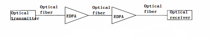
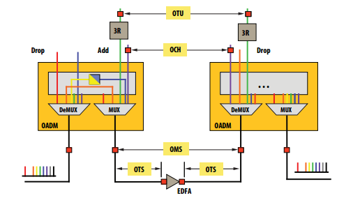
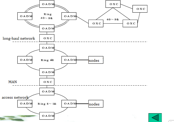
All-optical network (AON) is emerging as a promising network for very high data rates, flexible switching and broadband application support. In principle, all-optical network is founded on the premise of keeping the transmission and exchange of data signals entirely in the optical domain from source to destination, thus removing the intermediate electronics to eliminate the so-called electronic bottleneck and allow arbitrary signal formats, bit-rates, and protocols to be transported. In an all-optical network, data signals are always maintained in the optical domain except when they enter or exit the network, as shown in Figure 1. It means that there is no electrical signal processing in the entire transmission, so various transmission modes (PDH, SDH, ATM, etc.) can be applied in the AON to significantly improve the utilization of network resources. Being equipped with excellent transparency, survivability, scalability and compatibility, AON can achieve the data transmission of ultra-long haul, ultra-large capacity and ultra-high speed to become the preferred choice of the future high-speed broadband network.

An all-optical network

Figure 1: An all-optical network

3.Properties over the current optical communication network
AONs are able to arm the communication network with better manageability, flexibility and transparency. Compared with the traditional communication networks and the current optical communication networks, AONs are equipped with the following advantages that they don’t possess.
(1) AON provides huge bandwidth. Because the transmission and exchange of signals in AON entirely operate in the optical domain, AON can make the best use of the transmission capacity of fiber.
(2) AON achieves the transparent transmission. Adopting optical circuit switching to choose the routing according to wavelengths, AON is transparent to signal formats, bit-rates and modulation modes. That is to say, AON allows arbitrary signal formats, bit-rates, and protocols to be transported.
(3) AON has nice compatibility. Not only can AON be compatible with the current networks, but also AON is able to support the future broadband integrated services digital network (ISDN) as well as the network upgrade.
(4) AON possesses excellent scalability. Adding new nodes to the network has no effect on the original network architecture and node devices.
(5) AON is equipped with good reconfigurability. According to the requirements of communication capacity, AON can dynamically change the network architecture. AON is capable of recovering, building and removing the wavelength link.
(6) AON adopts lots of passive components to take place of the large photoelectric conversion equipments. Possessing simple configuration, AON is easy to maintain. At the same time, the overall exchange rate of AON can be greatly lifted to improve the reliability of network.

4.Key technologies
The key technologies applied in AONs fall into four categories: all-optical switching technology, optical cross connection (OXC) technology, optical add-drop multiplexing (OADM) technology, all-optical relay technology and optical amplifier technology.

4.1 All-optical switching technology
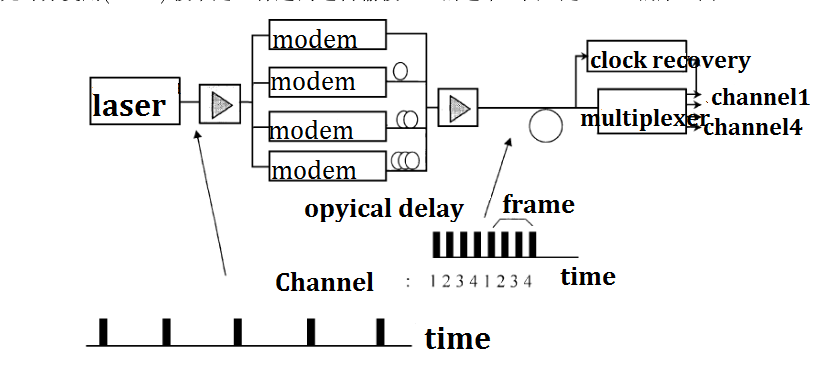
All-optical switching is the directly switching process which omits the OEO conversion to make full use of optical communication bandwidth. All-optical switching technology contains light-path switching technology and packet switching technology. The light-path switching can be divided into three types: space-division switching, time-division switching, wavelength/frequency-division switching. Asynchronous transfer mode (ATM), belonging to the packet switching technology, has been extensively studied.

4.2 OXC technology
OXCs are the devices applied in the optical network nodes to flexible and effectively manage the fiber transmission network by cross-connecting the optical signals. OXC technology is an important means of achieving the reliable network protection and recovery as well as automatic wiring and monitoring.

4.3 OADM technology
OADM, utilized in the optical network nodes, is able to selectively add or drop some wavelength signals as well as directly pass some wavelength signals without affecting other wavelength channel transmission. That is to say, OADM in the optical domain accomplishes the functions that SDH ADM does in time domain. OADM technology possesses transparency, thus able to deal with the signals of arbitrary formats and rates.

4.4 All-optical repeater technology
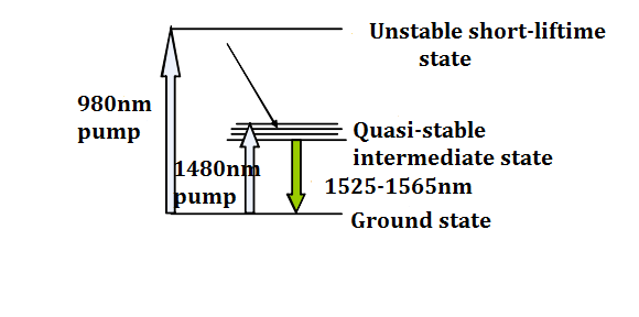
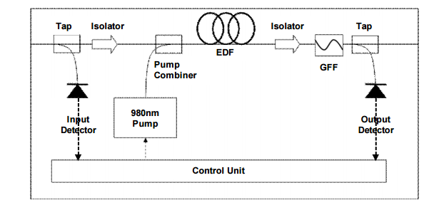
All-optical repeater technology is to directly amplify the optical signals in the optical path. Replacing the traditional OEO repeaters with the all-optical transmission repeaters, we can settle the problems of the repeater intricacy and electronic bottleneck to achieve the all-actinic signal transmission. The all-optical transmission repeaters include semi-conductor optical amplifier (SOA), Praseodymium-doped fiber amplifier (PDFA) and erbium-doped fiber amplifier (EDFA).

5.Main Components
In all-optical networks, a large quantity of optical components, which include active components and passive components. We will discuss five main components applied in all-optical networks.

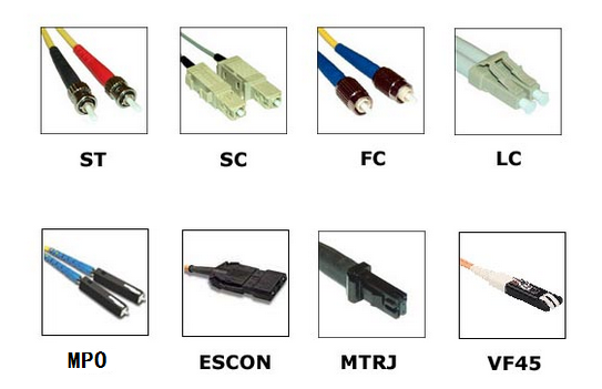
5.1 Optical connectors
Optical fiber connectors are used to join optical fibers where a connect/disconnect capability is required. The connectors mechanically couple and align the cores of fibers so light can pass. Fiber Optic Connectors according to connector structure can be divided into: FC,SC, ST, LC, D4, DIN, MU, MTP, MPO and so on in various forms. The optical interface is the physical interface used to connect fiber optic cable.

Optical connectors

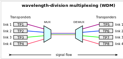
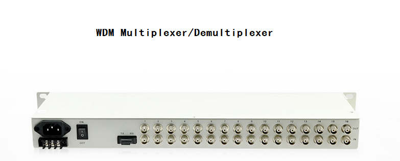
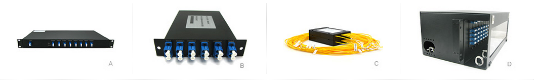
5.2 WDM multiplexer/demultiplexer
In a WDM system, multiplexers at the transmitter are used to join the signals together, and demultiplexers at the receiver are utilized to split them apart. According to different wavelength patterns, WDM multiplexer/demultiplexer can be divided into CWDM multiplexer/demultiplexer and DWDM multiplexer/demultiplexer.

Multiplexer Demultiplexer

5.3 OADM
An optical add-drop multiplexer (OADM) is a device used in wavelength-division multiplexing systems for multiplexing and routing different channels of light into or out of asingle mode fiber (SMF). CWDM OADM is designed to optical add/drop one multiple CWDM channels into one or two fibers. DWDM OADM is designed to optical add/drop one multiple DWDM channels into one or two fibers.

OADM

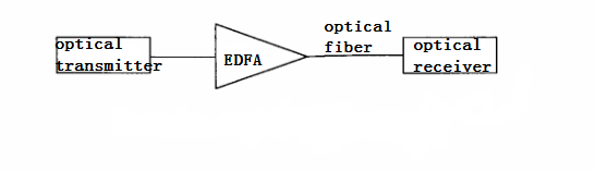
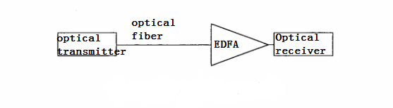
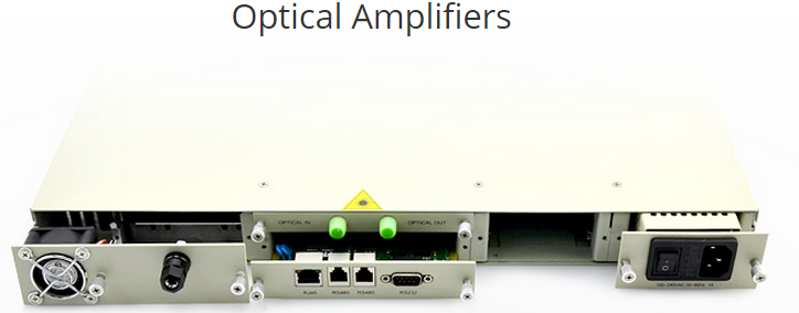
5.4 Optical amplifiers
An optical amplifier is a device that amplifies an optical signal directly, without the need to first convert it to an electrical signal.

Optical amplifiers

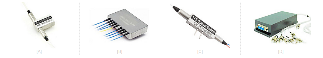
5.5 Optical switches
An optical switch is a device used to open or close an optical circuit which enables signals in optical fibers or integrated optical circuits (IOCs) to be selectively switched from one circuit to another in telecommunication. In a network system, optical switch plays an important role in protecting the path.

Optical switches

6.Development prospects
All-optical network is the developing goal of the optical communication networks. To achieve the integrated all-optical network, we will experience two phases of development. The first phase is to develop the optical communication network into the all-optical transmission network. During the whole point-to-point fiber transmission process, the photoelectric conversion is not required. The second phase is to achieve the integrated all-optical network. After fulfilling the whole point-to-point transmission, lots of functions, such as signal processing, signal storing, signal exchanging, signal multiplexing/demultiplexing and so on, needs to be completed by the photonic technology. Fulfilling the functions of transmitting, exchanging and processing the end-to-end optical signals is the second developing phase—-the integrated AON.

The Application of EDFA

Optical amplifiers are the critical technology for the optical communication networks, enabling the transmission of many terabits of data over distances from a few hundred kilometers to thousands of kilometers by overcoming the fiber loss limitation. As the first optical amplifier commonly used in optical communications systems, EDFA has resulted in a dramatic growth in transmission capacity with the deployment of WDM systems. Be equipped with the features of high output power, high gain, wide bandwidth, polarization independence and low noise figure, EDFAs have become one of the key components used in the new-generation optical communication system. So what is EDFA? Do you know EDFA working principle?

What Is EDFA?

Erbium-doped fiber amplifier (EDFA) is an optical repeater device that is utilized to boost the intensity of optical signals being carried through a fiber optic communications system. An optical fiber is doped with the rare earth element erbium so that the glass fiber can absorb light at one frequency and emit light at another frequency.

EDFA Working Principle

The erbium-doped fiber (EDF) is at the core of EDFA technology, which is a conventional silica fiber doped with Erbium. When the Erbium is illuminated with light energy at a suitable wavelength (either 980 nm or 1480 nm), it is motivated to a long-lifetime intermediate state, then it decays back to the ground state by emitting light within the 1525-1565 nm band. The Erbium can be either pumped by 980 nm light, in which case it passes through an unstable short lifetime state before rapidly decaying to a quasi-stable state, or by 1480 nm light in which case it is directly excited to the quasi-stable state. Once in the quasi-stable state, it decays to the ground state by emitting light in the 1525-1565 nm band. This decay process can be stimulated by pre-existing light, thus resulting in amplification. EDFA working principle is shown in the Figure 1.

EDFA working principle

Figure 1: EDFA working principle.

Baisc configuration of EDFA

EDFA configuration is mainly composed of an EDF, a pump laser, and a component (often referred to as a WDM) for combining the signal and pump wavelength so that they can propagate simultaneously through the EDF. In principle, EDFAs can be designed such that pump energy propagates in the same direction as the signal (forward pumping), the opposite direction to the signal (backward pumping), or both direction together. The pump energy may either be 980 nm pump energy, 1480 nm pump energy, or a combination of both. Practically, the most common EDFA configuration is the forward pumping configuration using 980 nm pump energy, as shown in the Figure 2.

EDFA-configuration

Figure 2: The EDFA configuration with 980 nm pump energy

Application of EDFA

After learning what is EDFA, and EDFA working principle. Next, we’ll discuss application forms and application fields of EDFA.

Forms of application
  • Booster Amplifier

When used as the booster amplifier, EDFA is deployed in the output of an optical transmitter to improve the output power of the multi-wavelength signal having been multiplexed, as shown in Figure 3. In this way, distances of optical communication transmission can be extended. This application form places a demand of higher output power on EDFA.

The booster amplifier

Figure 3: The booster amplifier

  • Preamplifier

When used as the preamplifier, EDFA needs the features of low noise and high gain. Being equipped with these features, EDFA can significantly improve the sensitivity of an optical receiver when deployed in the input of an optical receiver, as shown in Figure 4.

The preamplifier

Figure 4: The preamplifier

  • Line Amplifier

When used as the line amplifier, EDFA is able to periodically compensate for the transmission loss of lines. As a substitute for OEO repeater, EDFA can directly amplify the optical signals transmitted in lines. In this way, we solve the bottleneck problems of photoelectric interchange to lay a foundation for all-optical network (AON). Figure 5 shows this application of EDFA.

The line amplifier

Figure 5: The line amplifier

Fields of application

EDFA has the following fields of application:

(1) EDFA can be employed in the high-capacity and high-speed optical communication system. The application of EDFA is very constructive to deal with the problems of low sensitivity of receivers and short transmission distances owing to a lack of OEO repeater.

(2) EDFA can be utilized in long-haul optical communication system. By utilizing EDFA, we can dramatically lower construction cost by increasing the repeater spacing to reduce the quantity of regenerative repeaters. The long-haul optical communication system mainly includes the land trunk optical transmission system and the submarine optical fiber cable transmission system.

(3) EDFA can be used in the optical fiber subscriber access network system. If the transmission distances are too long, EDFA will function as the line amplifier to compensate for the transmission losses of lines, thus greatly increasing the number of subscribers.

(4) EDFA can be employed in wavelength-division multiplexing (WDM) system, especially dense wavelength-division multiplexing (DWDM) system. Utilization of EDFA in WDM system is able to solve the problems of insertion loss and reduce the influences of chromatic dispersion.

(5) EDFA can be utilized in community antenna television (CATV) system. In CATV system, EDFA functions as the booster amplifier to greatly improve the input power of an optical transmitter. Utilizing EDFA to compensate for the insertion loss of optical power splitters can significantly enlarge the scale of the distribution network and increase the number of subscribers.

Conclusion

From the above, we have a good understanding of EDFA, including EDFA working principle and its application. Of the various technologies available for optical amplifiers, EDFA technology is by far the most advanced. Nowadays EDFA is extensively in the optical fiber communication networks. As communication technologies continue to be developed, EDFA will become the preferred choice for the future optical amplifiers. Being equipped with the features of flat gain over a large dynamic gain range, low noise, high saturation output power and stable operation with excellent transient suppression, EDFA will play a more and more important role in optical communication system to better serve subscribers.

Related Articles:
Optical Amplifier – EDFA (Erbium-doped Fiber Amplifier) for WDM System
Differences Between Pre-Amplifier, Booster Amplifier and In-line Amplifier

The Comparison Of WDM And TDM

The Principles of WDM and TDM System
Wave-division multiplexing (WDM) is a technology which multiplexes a number of optical carrier signals onto a single optical fiber by using different wavelengths (i.e., colors) of laser light, as is shown in Figure 1.This technique enables bidirectional communications over one strand of fiber, as well as multiplication of capacity. As an analog process, WDM is based on a well-known concept called frequency division multiplexing (FDM). With this technology, the bandwidth of a channel is divided into multiple channels, and each channel occupies a part of the large frequency spectrum. In WDM networks, each channel is referred to as a wavelength. This name is used because each channel operates at a different frequency and at a different optical wavelength. The wavelengths on the fiber are separated by unused spectrum. This practice makes the wavelengths separate from each other and helps prevent their interfering with each other. This idea is called channel spacing, or simply spacing.

The-WDM-operating-principle

Figure 1: WDM operating principle

Time-division multiplexing (TDM) is a technology of transmitting and receiving independent signals over a common signal path by means of synchronized switches at each end of the transmission line so that each signal appears on the line only a fraction of time in an alternating pattern, as is shown in Figure 2. TDM is a type of digital (or rarely analog) multiplexing in which two or more bit streams or signals are transferred simultaneously as sub-channels in one communication channel, but are physically taking turns on the channel. The time domain is divided into several recurrent time slots of fixed length, one for each sub-channel. A sample byte or data block of sub-channel 1 is transmitted during time slot 1, sub-channel 2 during time slot 2, etc. One TDM frame consists of one time slot per sub-channel plus a synchronization channel and sometimes error correction channel before the synchronization. After the last sub-channel, error correction, and synchronization, the cycle starts all over again with a new frame, starting with the second sample, byte or data block from sub-channel 1, etc.

The-TDM-operating-principle

Figure 2: TDM operating principle

The Features of WDM and TDM
WDM, possessing high transmission capacity, can save optic fiber resources. As to the single-wavelength fiber system needs to use a pair of optic fibers to receive and dispatch a signal, while the WDM system, no matter how many signals waited to be transmitted, only needs a pair of optic fibers. Being transparent to various service signals, WDM is able to transmit different kinds of signals, then compounding and decomposing them. As an optimal capacity-expanding method, WDM can introduce various services or expand capacity only by means of changing switch and adding an optical wavelength instead of using lots of fibers or high-speed networking devices. What’s more, using the optical add-drop multiplexer (OADM) and the optical cross connection (OXC), WDM can constitute the all-optic network of high flexibility, high reliability and high survivability.

TDM is designed to accomplish the high-capacity and high-speed transmission. Being able to adopt nonlinear soliton transmission and other useful technologies, TDM can eliminate the effect of chromatic dispersion in the high-speed transmission. At the same time, TDM is able to eliminate the rate effect of electronic devices to accomplish the high-speed transmission on a single wavelength. As an effectively optical multiplexing way, TDM can make full use of spectral resources and greatly improve the utilization of spectral bandwidth. Unlike WDM, TDM is free of the limitations resulted from the nonlinear effect of fibers, thus effectively utilizing optical wavelength and operating in various network of different distances and capacities. Though still immature, TDM is a more long-term technology than WDM.

The Differences between WDM and TDM
TDM and WDM are two methods of multiplexing multiple signals into a single carrier. Multiplexing is the process of combining multiple signals into one, in such a manner that each individual signal can be retrieved at the destination. Since multiple signals are occupying the channel, they need to share the resource in some manner.

The primary difference between WDM and TDM is how they divide the channel. WDM divides the channel into two or more wavelength ranges that do not overlap, while TDM divides and allocates certain time periods to each channel in an alternating manner. Due to this fact, we can say that for TDM, each signal uses all of the bandwidth and some of the time, while for WDM, each signal uses a small portion of the bandwidth and all of the time.

TDM provides greater flexibility and efficiency, by dynamically allocating more time periods to the signals that need more of the bandwidth, while reducing the time periods to those signals that do not need it. WDM lacks this type of flexibility, as it cannot dynamically change the width of the allocated wavelength.

WDM proves much better latency compared to TDM. Latency is the time it takes for the data to reach its destination. As TDM allocates time periods, only one channel can transmit at a given time, and some data would often be delayed, though it’s often only in milliseconds. Since channels in WDM can transmit at any time, their latencies would be much lower compared to TDM. WDM is often used in applications where latency is of utmost priority, such as those that require real-time information.

The Relationship between WDM and TDM
WDM and TDM are all ultrafast transmission technologies. TDM has dispelled the restriction of the speed of the electronic device and is free of the limitation of the nonlinear effect of fibers, realizing high-speed transmission on the single wavelength, but it is still at research and development stage for the present. As to WDM, it is a very mature technology and extensively used in communication networks, but its multiplexing wavelength and transmission diatance are restricted by the nonlinear effect of fibers. In the long term, WDM and TDM can be used in tandem and co-exist in the transmission network. As is shown in Figure 3, we can build a bigger optical transmission network by using TDM high-speed channels to connect the subnets composed of WDM. In the subnets, WDM can significantly improve flexibility and reliability of network. At the same time, TDM is effective to accomplish the high-speed and high-capacity transmission.

The-optical-transmission-network-of-WDM-and-TDM

Figure 3: The optical transmission network of WDM and TDM

Conclusion
WDM, as a mature and high-capacity optical transmission technology, has already been extensively adopted in the network now. It is equipped with the advantages of transparency, reconfigurability and excellent network survivability. The future WDM optical network will develop towards the flexible networking direction based on the optical wavelength routing and exchanging, which possesses the ability of fast network recovery and reconfiguration and will play a main role in the future optical transmission network. As a very effective multiplexing technology, TDM can make full use of spectral resources and dispel some restrictions of WDM system caused by nonlinear effect. In recent years TDM has made great progress in the research field, but not ripe enough. In a nutshell, WDM and TDM have their own advantages and disadvantages as the optical multiplexing technology. With the relevant study lucubrating constantly, WDM and TDM can be combined together to be extensively applied to the ultra fast transmission network.

Related Article: Different Ports on WDM Mux/Demux

Difference Between SONET/SDH and DWDM

The OTN Online Tutorial

OTN Tutorial: Introduction

As we known, the core of most current operator networks is the asynchronous digital hierarchy/ synchronous optical network (SDH/SONET), which has always offered good fault management, performance monitoring, predictable latency, a protection mechanism and, of course, synchronization. However, nowadays a significant rise in bandwidth demand associated with video services and an increasing use of local area networking (LAN) and storage area networking (SAN) drive the need for optical transport network (OTN), which is the new-generation backbone transmission network based on WDM techniques with the dual advantages of SDH/SONET and WDM and the ability of meeting the requirements of various services, as a transport technology for point-to-point transmission application in core/long-haul networks and for aggregation/switching applications in metro networks. As the optimal choice for developing the transport network, OTN is playing a more and more important role in the transport network. This article is written to give you a sound understanding of OTN tutorial through introducing its structures and application.

OTN Tutorial: The Hierarchical Structure

An OTN introduces three main sublayers: an optical channel (OCH), an optical multiplexing section (OMS), an optical transmission section (OTS). The hierarchical structure is shown in Figure 1. The OCH layer provides an end-to-end connection in a unit of wavelength for various services’ signals from the electric layer. What the OMS layer accomplishes is to multiplex and demultiplex lots of signals from the OCH layer. The OTS layer deals with the physical transmission problems of optical signals in specifically optical media. A client-server model is applied between sublayers of OTN. Each sublayer offers well-defined services to its client layers and each sublayer has its own layer-management functions including fault, performance, and configuration management. An OCH layer consists of many OMS layers and an OMS layer is made up of numerous OTS layers. So if the bottom layer breaks down, it certainly affected the correspondingly upper layers.

OTN Tutorial

Figure 1: The hierarchical structure of OTN

OTN Tutorial: The Frame Structure

Speaking to the frame structure of OTN, we should first refers to the digital wrapper technology. OTN uses the digital wrapper technology to wrap each wavelength into a digital envelope consisting of a overhead section, a forward error correction (FEC) section and a payload section (Figure 2). The overhead section lies in the head of a digital envelope, which is used to load the overhead bytes. With those bytes, OTN can execute the networking management functions through network transmission. The FEC part is located in the tail, which is applied to load the FEC codes and partly perform the detection and correction of errors. By minimizing the errors, FEC plays a key role in expanding distance between optical sections and increasing transmission rate. Between the header and tailer is the payload section, which is employed to load all kinds of networking protocol data packages without changing them.

20150414181256

Figure 2: The digital envelope

A frame in OTN is called an optical channel transport unit (OTU), which is brought into being by means of the digital wrapper technology adding the overhead section and the FEC section into client signals. There are three rates of OTU-k (k=1,2,3): 2.5Gb/s, 10Gb/s and 40Gb/s in standard G.709. An OTU-k is composed of four parts: an optical channel payload unit (OPUK), an optical channel data unit (ODUK), an optical channel transport unit (OTUK) and an FEC. An OPUK section is made up of a overhead and a payload. The overhead part contains the adapted information used for supporting specific clients and each client has his/her own overhead structure, while the payload part includes client signals adopting specific mapping technology. An ODUK section offers cascade connection monitoring and end-to-end channel monitoring, including numerous overhead fields such as path performance monitoring (PM), tandem connection monitoring (TCM), automatic protection switching (APS), protection communication control channel (PCC), etc. An OTUK part is mainly applied to monitor the state of transmission signals between regenerative nodes. Asis mentioned above, the FEC part is applied to load the FEC codes and partly perform the detection and correction of errors to minimize emerging errors. The frame structure is as below (Figure 3).

20150415112426

Figure 3: The frame structure of OTN

OTN Tutorial: The Topological Structure

The topological structure of OTN includes the logical structure describing the routes of information flow in network and the physical structure describing the practical distribution and the connection ways of nodes or fiber media used to connect nodes. The logical structure is divided into the dual-loop structure and the daisy-chaining structure, and the former is the optimal choice because the dual-loop structure provide the better recovering ability of systems in the breakdown situation to guarantee the high-quality service and offer an reliable and effective network for clients. The physical structure includes point-to-point configuration (Figure 4), star configuration (Figure 5), ring configuration (Figure 6) and linear configuration (Figure 7), which is relatively simple and follow standard installing convention. These physically topological structures can be flexibly and collocationally used according to client needs. To guarantee the high reliability and perform the flexible bandwidth management, the ring configuration is extensively applied in the core/long-haul network , the metropolitan area network (MAN) and the access network, as is shown in Figure 8. In the whole ring configuration, we will uses such products as optical add-drop multiplexer (OADM), optical cross connection (OXC), etc.

20150415141252

Figure 4: The point-to-point configuration

20150415141224

Figure 5: The star configuration

20150415141237

Figure 6: The ring configuration

20150415144525 (2)

Figure 7: The linear configuration

20150415144525 (1)

Figure 8:The ring configuration in long-haul network, MAN and access network

OTN Tutorial: The Application

Comprehensively considering the hierarchical relationships of existing transport network, the distributing features of the transmission particles and the different states of OTN devices, OTN is extensively applied in the core layer of the long-haul transmission network and the MAN. Nowadays the core MAN facing the situation of digital services soaring, but the IP digital network fails to meet these services’ requirements owing to a lack of sufficient protection and recovery abilities. The photoelectric cross device of OTN could be used to solve the current problem of the MAN. Introducing OTN in the core MAN, we can offer plenty of bandwidth resources for the IP digital network and provide the carrier-class protection for digital services to significantly the service quality of digital services. At the same time, we also save the interface resources of router to low the requirement for router capacity and offer the protection and recovery of mesh network. The long-haul transmission network is to perform the transmission of services without refering to the complicated service scheduling and crossing. Adopted in the long-haul network, OTN can greatly facilitate the fault monitoring and operating management of systems with its rich overhead bytes. Being able to transparently transmit signals, OTN enables routers to use 10GE digital interfaces instead of expensive POS interfaces when facing lots of soaring digital services in the long-haul network. What’s more, OTN contributes a lot to achieving all-sided optical crossing in the future with the ability to combine itself with intelligent surfaces.

Conclusion

As the optimal choice for the technological developmemt of the transmission network, it is predictable that OTN will be extensively used in the near future to become the preferred transmission network for operators and clients. I hope you can get a further understanding of OTN  tutorial after reading this article. If you want know more about OTN product, please visit FS.COM, which provides a comprehensive line of networking devices including patch panel, network switch and so on.

Related Articles:
What Is OTN — Optical Transport Network?
Difference Between SONET/SDH and DWDM

Why Is OTN Becoming More And More Important?

In an era of various services operating, telecom operators will be transformed into the comprehensive service providers of information and communications technology (ICT).The abundant services drive the higher demand for broadband services, directly manifesting the requirement for the ability and performance of the transport network. Owing to meet the needs of all kinds of new services, the Optical Transport Network (OTN) technology comes into being, playing a leading role in the transport network.

OTN, the next-generation backbone transmission network based on WDM techniques, lies in the optical layer network. Standardized by a series of ITU-T advice covering G.872, G.709 and G.798, it is the new generation of digital transmission network and optical transmission network. OTN is based on a fixed frame size with 3 key sections: Overhead, Payload, and Forward Error Correction (FEC). These OTN frames are routed across the network in a connection-oriented way. Similar to a synchronous digital hierarchy/ synchronous optical network (SDH/SONET) frame, the overhead carries the information required to identify, control and manage the payload to maintain the deterministic quality. The payload is simply the data transported across the network, while the FEC corrects errors when they arrive at the receiver. The number of correctable errors depends on the FEC type. The most common is GFEC described in the G.709 standard, which can identify 16 symbol errors and correct 8 symbol errors per frame. As is shown in Figure 1, the OTN concretely operates as follows. What OTN successfully deals with are the traditional WDM net working issues of missing wavelength, weak scheduling ability of subwavelength services, bad networking ability and poor protection ability. Combining the strength of optical-field handling with that of electrical-field treatment, it is the optimal technology for transmitting the large-particles broadband services, providing the huge transmission capacity, the completely transparent connection of end-to-end wavelength and subwavelength as well as the various protection at telecommunication level.

Figure 1:The operation of an OTN network

The core of most current operator networks is SDH/SONET, which has always offered good fault management, performance monitoring, predictable latency, a protection mechanism and, of course, synchronization. This very stable network has become the expected minimum in performance objectives for network operators today and is often described as having “five 9s” (and higher) performance, meaning at least 99.999% up time. On the basis of the current SDH/SONET managerial functions, ONT provides not only the complete transparency of communication protocols, but also the ability of end-to-end connection and networking for WDM, whose technology inherited the dual advantages of SDH and WDM. It solves the SDH issues that the cross particles based on VC-12/VC4 are too small to meet the transmission requirements of large particles services,causing the complicated schedule. At the same time, it also partly settles the WDM problems of the positioning difficulty due to a system fault, weak networking and poor ability and means to provide the network survivability. OTN reduces transport costs and delivers enhanced network and performance management functions. Forward error correction (FEC) algorithms improve the reach of the transmission links, helping to reduce regenerators and optimize the spectral efficiency. Additionally, an OTN “digital wrapper” includes many layers and components known from SDH/SONET but at enhanced performance levels.

The ever-increasing demand of broadband services has significantly contributed to the application of OTN, which is simpler and better than SDH/SONET and increases the scalability of WDM systems. OTN technology comes into being, not only following the development of the communication technology, but also impelling the transmission network to a better stage. What’s more, the transmission requirements of IP services and the adapter IP services OTN facing has become an important issue that the optical communication further develops. As the optimal choice for developing the transport network, OTN is becoming more and more important, and will be extensively applied to play a dominant role in the transmission network in the future!