Guide to Fiber Optic Attenuator

Fiber optic attenuators are devices that precisely decrease the optical power in fiber links by a fixed or adjustable amount. They can not only control the power level of optical signals, but also are used to test the linearity and dynamic range of photo sensors and photo detectors. Fiber optic attenuator has a number of different forms and is typically divided into fixed or variable attenuators. What’s more, they can be classified as LC, SC, ST, FC, MU, E2000 etc. according to the different types of connectors. This article will make a brief introduction of fiber attenuator to help you better understand it.

fiber optical attenuators

Why We Need Fiber Optic Attenuator?

As is known to all, the optical power at the receiver ultimately decides the ability of any fiber optic system to transmit data. But it isn’t the fact that the bigger signal power level is better. The truth is that either too little or too much power will cause high bit error rates. Too much power can make the receiver amplifier saturates, while too little will cause noise problems as it interferes with the signal.

Typically, the receiver power depends on two basic factors: the power launched into the fiber and the lost power by attenuation in the optical fiber cable plant. When the power is too high, fiber optic attenuator can help by reducing receive power for better performance. Generally, multimode systems do not need optical attenuators because they barely have enough power output to saturate receivers. While single mode systems, especially for short links, desperately need attenuation because they often have too much power. But nowadays, the complexity of telecommunications requires attenuation both in single mode and multimode systems.

Operating Principles of Fiber Optic Attenuator

There are many methods of power attenuation, including absorption, reflection, diffusion, scattering, deflection, diffraction, and dispersion, etc. Optical attenuators usually operate by absorbing the light, like a neutral density thin film filter. Or they work by scattering the light such as an air gap. Another type of attenuators uses the length of high-loss optical fiber, that operates upon its input optical signal power level in such a way that its output signal power level is less than the input level.

Fixed Fiber Optic Attenuators VS Variable Optical Attenuators

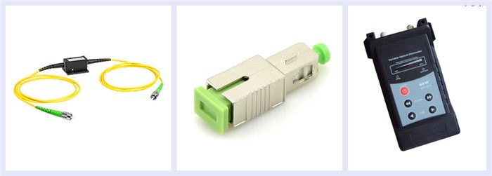
Fiber optic attenuators can be divided into two categories: fixed optical attenuator and variable attenuator. Both of them have unique characteristics.

Fixed Fiber Optical Attenuators

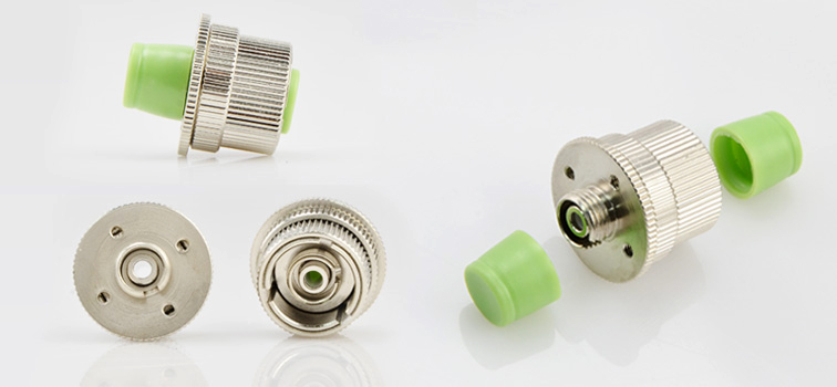
Fixed optical attenuators are compact adapter styles that can reduce signals by a specific amount. As the signal approaches a device or node in a communication link, the power is reduced to a level that is suitable for its application. They can make signal reflection less of an issue and therefore make for more accurate transmissions of data. Fixed attenuators are available with single mode, multimode and polarization maintaining fiber. And they are ideal for attenuating single mode fiber connectors in various application, such as LAN (Local Area Network), CATV (Community Access Television) and telecommunication networks.

fixed fiber optical attenuators

Variable Fiber Optical Attenuators

Variable fiber optic attenuators are rugged, hand-held devices that are used for testing and measurement, or equalizing the power between different signals. They can offer a range of attenuation values with flexible adjustment. Because variable attenuators work by directly blocking the beam, they are polarization insensitive. Like fixed attenuators, variable optic attenuators are also offered with single mode, multimode, or polarization maintaining fibers.

variable fiber optic attenuator

Conclusion

Fiber optical attenuators are key components in optical telecommunication systems. They can adjust optical signal levels to increase network flexibility and providing management of optical power. Besides fixed fiber optical atternuators and variable attenuators, there are many other types atternuators, such as loopback attenuators, built-in variable attenuators and so on.

Related Article:
Guideline for Fixed Fiber Attenuator 

The value-added function of the modulator based on indium phosphide equipment

Indium phosphide (InP) is a binary semiconductor composed of indium and phosphorus. InP is used in high-power and high-frequency electronics because of its superior electron velocity with respect to the more common semiconductors silicon and gallium arsenide. It also has a direct bandgap, making it useful for optoelectronics devices like laser diodes. InP is also used as a substrate for epitaxial indium gallium arsenide based opto-electronic devices.

The Inp material system has a rich history as an integration platform. The complementary functions or features discussed here have been demonstrated either integrated with Inp-based MZMs, or in epitaxial growth structures compatible with Inp-based MZMs.

The main works of the Inp material system is deep helium implantation has been used to creat point defects in zinc doped InP layers to remove carriers from participating in conduction, with minimal impact to the optical waveguide properties. This helium implant process can be used to isolate electrodes and has been shown to remain stable under extensive thermal, electrical, and optical stress conditions.

Evanescently coupled waveguide InGaAs power detectors insensitive to the optical signal wavelength and input power have been monolithically integrated with the Inp-based MZM, as a simple extension of the spot-size converter fabrication process. These detectors are placed on the complementary and/or in-line out put waveguides to provide feedback for transmitter control.

Leuthold and Joyner have proposed a method to actively tune the power splitting ratio in a 2 x 2 MM and the active tuning of the cross/bar MM1 power splitting ratio betwwen 1 and > 1.7 is demonstrated. The tuning is achieved for < 3 mA of applied current to helium implant isolated edge electrodes on a 10.3 micron 2 x 2 MMI and it produces < 0.15 dB optical loss. This split ratio dynamic range, if applied to the 2 x 2 MMI combiner in the zero chirp modulator design presented, produces sufficient optical power imbalance to move between zero chirp and he optimal negative chirp for maxium dispersion limited reach. A current tunable MMI has also been demonstrated using selective zinc diffusion.

An output power variable fiber optic attenuator is a commonly required function in transmitters for pratical optical communication systems. Early fixed wavelength MZM transmitters used integrated electroabsorption pads on the input of the InP-based MZM to provide this variable optical attenuator function. The same processes used to implement the MMI tunable power optical splitter could be used to implementa wavelength independent variable optical attenuator is simple. The 1 x 1 MMI is a rest ricted symmetric interference device in which only even modes are excited. Therefore, by asymmetrically modifying the refractive index along a selected cross section within the MMI waveguide, such that a phase change of π is induced, mode conversion of the even modes into odd modes is realized. The odd modes are rejected at the MMI output waveguide.

FC Type Variable Fiber Optic Attenuator 1 to 30dB Range

Semiconductor optical amplifiers have been integrated prior to MZMs that use InGaAsP/InP MQW cores, and lossless operation has been demonstrated in 10 Gb/s 1MDD and 40 Gbit/s DPSK applications.

Future applications will benefit from exploration of a single Inp chip for dual polarization Cartesian MZMs, through the monolithic intergration of a TE to TM polarization converter and a polarization combining waveguide element. The demonstrated polarization manipulation functions in InP materials have not used waveguide structures compatible with an MZM. THis commercial application will hopefully spur further reasearch in this area.

Welcome to fiberstore to ask much more questions about fiber optical attenuator, we will provide attentive service for anyone. http://www.fiberstore.com/

Article Source: http://www.fiber-optical-networking.com/