
In optical communication, duplex and parallel optical links are two of the most commonly deployed cabling structures. This post will discuss some specific connectivity solutions using 2-fiber duplex and 8-fiber/20-fiber parallel fiber optic modules.
A duplex link is accomplished by using two fibers. The most commonly used connector is the duplex LC. The TIA standard defines two types of duplex fiber patch cables terminated with duplex LC connector to complete an end-to-end fiber duplex connection: A-to-A patch cable (a cross version) and A-to-B patch cable (a straight version). In this article the LC to LC duplex cables we use are all A-to-B patch cables. It means the optical signal will be transmitted on B connector and received on A connector.
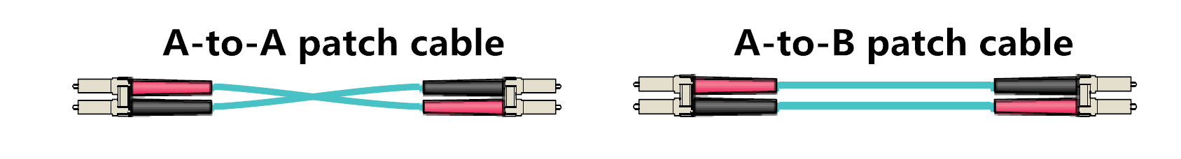
Figure 1: two types of fiber patch cables
A parallel link is accomplished by combining two or more channels. Parallel optical links can be achieved by using eight fibers (4 fibers for Tx and 4 fibers for Rx), twenty fibers (10 fibers for Tx and 10 fibers for Rx) or twenty-four fibers (12 fibers for Tx and 12 fibers for Rx). To accomplish an 8-fiber optical link, the standard cabling is a 12-fiber trunk with an MTP connector (12-fiber connector). It follows the Type B polarity scheme. The connector type and the alignment of the fibers is shown in figure 2.
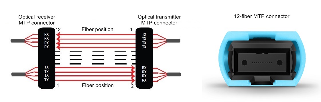
Figure 2: parallel fiber (8-fiber) optic transmission
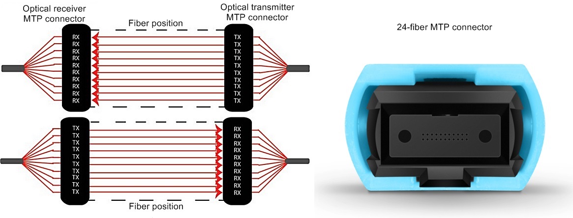
To accomplish a 20-fiber parallel optical link, a parallel 24-fiber MTP connector is used. Its fiber alignment and connector type is shown in figure 3.
We will discuss the items required to connect two duplex transceivers in this part. These 2-fiber duplex protocols include but not limited to: 10GBASE-SR, 10GBASE-LR, 10GBASE-ER, 40GBASE-BiDi, 40GBASE-LR4, 40GBASE-LRL4, 40GBASE-UNIV, 40GBASE-FR, 100GBASE-LR4, 100GBASE-ER4, 100GBASE-CWDM4, 100GBASE-BiDi, 1GFC, 2GFC, 4GFC, 8GFC, 16GFC, 32GFC.
When directly connecting two duplex SFP+ transceivers, an A-to-B type patch cable is required. This type of direct connectivity is suggested only to be used within a given row of racks/cabinets. Figure 4 shows two SFP+s connected by one LC to LC duplex patch cable.
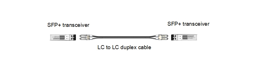 Figure 4: 2-fiber to 2-fiber direct connectivity
The following figure is an interconnect for two duplex transceivers. An 8-fiber MTP trunk cable is deployed with 8-fiber MTP-LC breakout modules connected to the end of the trunk. It should be noted that the polarity has to be maintained during the transmission. And pinned connectors should be deployed with unpinned devices. Structured cabling allows for easier moves, adds, and changes (MACs). Figure 5 illustrates this solution.
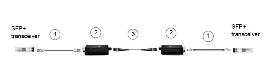
Figure 5: 2-fiber to 2-fiber interconnect (1)
| Item | Description |
| 1 | LC to LC duplex cable (SMF/MMF) |
| 2 | MTP-8 to duplex LC breakout module (pinned) |
| 3 | 8 fibers MTP trunk cable (not pinned) |
Figure 6 is also an interconnect solution for SFP+ transceivers, but on the right side an 8-fiber MTP to 4 x LC harness cable and an MTP adapter panel are used instead. This solution works best when connectivity is required for high port count switch.
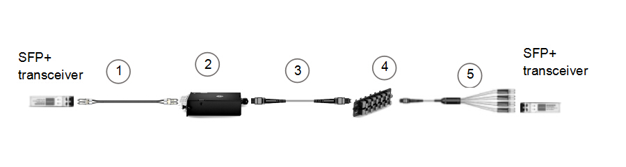
Figure 6: 2-fiber to 2-fiber interconnect (2)
| Item | Description |
| 1 | LC to LC duplex cable (SMF/MMF) |
| 2 | MTP-8 to duplex LC breakout module (pinned) |
| 3 | 8 fibers MTP trunk cable (not pinned) |
| 4 | 96 fibers MTP adapter panel (8 port) |
| 5 | 8 fibers MTP (not pinned) to duplex 4 x LC harness cable |
This solution is a duplex cross-connect. It will allow all patching to be made at the main distribution area (MDA) with maximum flexibility for port-to-port connection. Figure 7 illustrates the cross-connect solution for duplex connectivity.
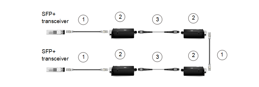
Figure 7: 2-fiber to 2-fiber cross-connect
| Item | Description |
| 1 | LC to LC duplex cable (SMF/MMF) |
| 2 | MTP-8 to duplex LC breakout module (pinned) |
| 3 | 8 fibers MTP trunk cable (not pinned) |
We will discuss items required to connect two parallel (8-fiber or 20-fiber) transceivers in this part. These protocols include but not limited to: 40GBASE-SR4, 40GBASE-xSR4/cSR4/eSR4, 40GBASE-PLR4, 40GBASE-PSM4, 100GBASE-SR4, 100GBASE-eSR4, 100GBASE-PSM4, 100GBASE-SR10.
When directly connecting two QSFP+ or QSFP 28 transceivers, an 8-fiber MTP trunk cable is needed. For directly connecting two CFP transceivers, a 24-fiber MTP trunk cable is needed.

Figure 9 shows an interconnect solution for two CFP modules (20-fiber). To break-out the CFPs to transmit the signal across an 8-fiber infrastructure, a 1 x 3 breakout harness (24-fiber MTP to three 8-fiber MTP) is required. To achieve an interconnect for two 8-fiber optics, we can replace the breakout harness by an 8-fiber MTP (pinned) trunk and the 24-fiber MTP trunk by an MTP (not pinned) trunk.
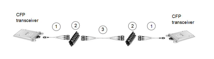
Figure 9: 20-fiber to 20-fiber interconnect
| Item | Description |
| 1 | 1×3 MTP breakout harness cable (24-fiber MTP to three 8-fiber MTP) (pinned) |
| 2 | 96 fibers MTP adapter panel (8 ports) |
| 3 | 24 fibers MTP trunk cable, three 8-fiber legs (not pinned) |
This post gives brief introduction to the meaning of duplex and parallel optical link and presents some connectivity solutions for two duplex optics or two parallel optics. The corresponding items used in each solution are listed too. The transmission distance and working environment should be taken into account when applying each cabling solution. The parallel to duplex connectivity solutions will be discussed in the next post.