
400 Gigabit Ethernet was planned to be released in December this year. It is designed to meet IEEE P802.3bs Task Force standard and to apply to both metro and long-haul networks. The 400GbE operates over 100 m of multimode fiber, 500 m of singlemode fiber, 2 km of SMF, and 10 km of SMF. 400G CDFP and CFP8 are two form factors of 400G Ethernet technology. This article would give a introduction to 400G CDFP and CFP8 modules and make a comparison between them.
The CDFP is short for 400 (CD in Roman numerals) Form factor Pluggable, which is designed to provide a low cost, high density 400 Gigabit Ethernet solution. It features as front panel, hot-pluggable, 16 channel and 400 Gbps module. CDFP will be a short reach module, which enables 4 Terabit line cards. From the perspective of interface, it is very similar to the QSFP and CXP module. CDFP developers have targeted using the developing IEEE802.3bs specification for Ethernet 400GBaseSR, 400GBaseLR.
- 5 meter direct attach cables
- 100 meter multimode fiber
- 500 meter parallel singlemode fiber
- 2 kilometers of duplex singlemode fiber
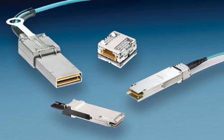
Figure2: 400G CDFP Module
Following CFP2 and CFP4 naming, CFP8 module was proposed in the year 2015. CFP8 is a new form factor which is still under development by members of CFP8 MSA. The form factor of CFP8 is amounting to CFP2, but it supports 4 × 100G and 400G, for example, 4×CFP2’s 1×100G. The CFP8 uses a new 16 × 25G electrical I/O connector. The CFP8’s interface has been generally specified to allow for 16 × 25 Gb/s and 8 × 50 Gb/s mode. From the point of bandwidth density, the CFP8 module is eight times larger than the CFP module and four times larger than the CFP2 module.
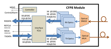
Figure3: 400G CFP8 module operation
Example IEEE specifications supported by CFP8:
- 400GBASE-SR16 parallel MMF (16x25G NRZ)
- 400GBASE-FR8/LR8 duplex SMF (8x50G PAM4 WDM)
- 400GBASE-DR4 parallel SMF (4x100G PAM4)
- CDAUI-16, CDAUI-8
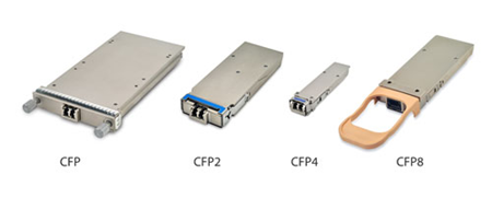
Figure4: Form factors of CFP modules
Among all the specifications on the above, 400GBaseDR4 is the most revolutionary one. 400GBaseDR4 uses 4x100G parallel SMF PAM4 signaling technology. This technology is also aimed at fitting in the CFP4 21.5-mm width module size, while using 12 (SMF) fibers within a 1×12 MPO optical connector and the host board electrical 56-pin edge connector.
Low power consumption is also a distinctive feature of CFP8. Active optical modules have been widely deployed in the process of data transmission, but some of them or some copper applications really cost a lot and consumes much power. CFP8 module uses internal mid-board optical or electrical interconnect flyovers and bulkhead MPO or MXC connectors to connect the switch. This reduces power consumption to a great extent.
CDFP was proposed earlier than CFP8, it has larger form factor than CFP8.
CDFP supports passive and active copper cable, active optical cable and multimode fiber while CFP8 supports singlemode and multimode fiber.
CFP8 modules support longer data link distance compared with CDFP modules.
The CDFP modules provide a very versatile solution for data center interconnects. CFP8 would be used in high-density 4x100GbE fan-out applications, such as datacom applications or in ITU-T for telecom applications.
This article mainly discussed about CDFP, CFP8 and their differences in form factor, supported fiber type, transmission distance and applications. There is no doubt that 400G Gigabit Ethernet is an irresistible trend for future Ethernet development.
Related Article: CFP Transceiver Module Overview: CFP, CFP2, CFP4 & CFP8