Fiber Optic Cable Basics

You hear about fiber optic cables whenever people talk about telephone system, cable TV system or the Internet. They are also used in medical imaging and mechanical engineering inspection nowadays. How much do you know the basic information of cables? For example, what a 9/125/250µm cable mean. In this article, we will show you some cable basics.

Cable Size

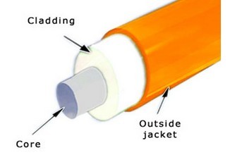
The size of the optical fiber is commonly referred to by the outer diameter of its core, cladding and coating. Example: 50/125/250µm indicates a fiber with a core of 50 microns, cladding of 125 microns, and a coating of 250 microns. The coating is always removed when joining or connecting fibers. A micron (µm) is equal to one-millionth of a meter. 25 microns are equal to 0.0025 cm. (A sheet of paper is approximately 25 microns thick).

Cable Types

Cables can be identified by the type of paths that the light rays, or modes, travel within the fiber core. Also according used in different environments, there are outdoor cable, waterproof cables, lszh cable, submarine optical cable, etc.

Distribution Cables

These cables are small in size, and used for short, dry conduit runs, riser and plenum applications. The fibers are double buffered and can be directly terminated, but because their fibers are not individually reinforced, these cables need to be broken out with a “breakout box” or terminated inside a patch panel or junction box.

Breakout Cables

They are suitable for conduit runs, riser and plenum applications. Because each fiber is individually reinforced, this design allows for quick termination to connectors and does not require patch panels or boxes. Breakout cable can be more economical where fiber count isn’t too large and distances too long, because is requires so much less labor to terminate.

Loose Tube Cables

These cables are composed of several fibers together inside a small plastic tube, which are in turn wound around a central strength member and jacketed, providing a small, high fiber count cable. This type of cable is ideal for outside temperatures and high moisture conditions(waterproof cables also do good jod in moisture conditions), as it made with the loose tubes filled with gel or water absorbent powder to prevent harm to the fibers from water. It can be used in conduits, strung overhead or buried directly into the ground.

Ribbon Cable

This cable offers the highest packing density, since all the fibers are laid out in rows, typically of 12 fibers, and laid on top of each other. This way 144 fibers only has a cross section of about 1/4 inch or 6mm! Some cable designs use a “slotted core” with up to 6 of these 144 fiber ribbon assemblies for 864 fibers in one cable! Since it’s outside plant cable, it’s gel-filled for water blocking.

Armored Cable

Used for rodent protection in direct burial if required. This cable is non-gel filled and can also be used in aerial applications. The armor can be removed leaving the inner cable suitable for any indoor/outdoor use. (Temperature rating -40ºC to +85ºC)

Indoor/Outdoor Cable

Indoor/Outdoor cables combine the flame resistance and safety features of an indoor riser or plenum cable with the durability that is critical for OSP use. The result is a unique, dual-purpose cable that can save time and money by allowing OSP applications to flow seamlessly indoors, using a single cable and no splices.

Aerial Cable

Aerial cables are for outside installation on poles. They can be lashed to a messenger or another cable (common in CATV) or have metal or aramid strength members to make them self supporting.

Special Cable

These cables combine specialty optical fiber with cabling construction that make installation or deployment easier and/or protect the fibers for long-term use in harsh environments.

Even more types of cables are available and also many brands cables from different manufacturers are available. Corning is one of the outstanding fiber optic cable manufacturers, who invented the first commercially viable low-loss optical fiber in 1970. Today Corning remains the global market leader in the industry, the corning fiber optic cable is recognized for their excellence and innovation.

FiberStore Launches New LSZH Fiber Optic Cable Series

FiberStore is introducing new families of Low Smoke Zero Halogen (LSZH) cables. LSZH cable is constructed utilizing the superior design and engineering standards to fit for aerial, direct buried, duct, general purpose horizontal, vertical riser applications.

“For work spaces with strict environment or safety regulations or where ventilation is a concern, FiberStore’s LSZH cables provides a solution that supports both compliance to strict NFPA 70guidelines as well as greatly reduces potentially toxic emissions when subjected to high heat or flame conditions,” stated Wilson John, commercial manager for bulk fiber cable at FiberStore

zero halogen cables

LSZH Loose Tube Cables

LSZH Loose Tube Cables are double-Jacket wich are designed for industrial building backbones and harsh environments atyptial of traditional datacom system. With two durable LSZH jackets, these cables are ideal for applications requiring the added mechanical and environmental protection. Double Jacket combines flexibility with extra mechanical protection for a durable, reliable cabling solution that is easy to handle and install. Due to halogens in the jacket compound, these cables pose little risk in the controlled and protected environment of typical building air spaces, such as behind walls, under floors and in conduit.

LSZH cable with Metal Strength member FTTH Cable

LSZH metal strength menber FTTH cable include FTTH indoor cable, drop cable and armored duct cables.

Armored Duct cables are designed for use in direct installation in villas and multi dwelling units. With two parallel Metal strength members ensure good performance of crush resistance to protect the fiber.There was a layer of skin resistance hose and a layer of aluminum tape armored, let the cable can adapt to all kinds of bad environment and artificial damage.

FTTH Drop Cables with two parallel metal strength members ensure good performance of crush resistance to protect the fiber. A steel wire as the additional strength member is also applied to ensure good performance of tensile strength. The LSZH sheathed with high flame resistance enables the FTTH drop cable can operate in high-temperature. This cables is mainly designed for indoor riser level and plenum level cable distribution and between instruments, communciation equipments.

FTTH indoor cables with LSZH jacket are novel flute design with metal strength member. this cable is suitable for indoor and outdoor along the wall, roof, sandwich and duct connected directly cloth fiber optic cable to standard and solid structure design produce communication equipment tail fiber and activity connecting line can be applied directly to the connection between the equipment.

LSZH cable with FRP & KFRP Strength member FTTH Cables

Low smock zero halogen cables FRP & KFRP Strength member FTTH cables also include FTTH indoor, drop, and armored duct types.FTTH indoor cables with LSZH jacket are designed for use in horizontal, vertical, and corner cabling. With two parallel FRP & KFRP strength members to ensure good performance of crush resistance and protect the fiber. Its special low-bend-sensitivity fibers provide high bandwith and excellent communciation transission property.

LSZH Armored FTTH duct cable are designed for use in direct installation in villas and multi dwelling units. There are a layer of skiin resistance hose land a lay of alluminum tape armored, let the cable can adapt to all kinds of bad environment and artifical damage. Two sheath of the cables will protect the FTTH duct cables from Rat bit and other damage.

FTTH drop cable with FRP & KFRP stength member is optical communication unit in the center, which can realized the telephone, data, cable TV’s combinatiion of three nets and video monitoring. With small diameter, water-resistant, soft and bendable featuers, the cable is suitable for plenum level cable distributin and indoor riser levels as well as installations between instruments and communications equipments.

Besides, FiberStore also provides single mode gel-filled ribbon LSZH indoor/outdoor riser cables. These cables can maximized the use of criticl dust space with excellent installtion results as their smallest and lightes standard. The precise fiber and ribbon geometries result in excellent mass splicing yields. Cables are available in preconnectiorized assemblies which made easy field installation and reduced labor costs.

All of FiberStore low smoke halogen free cables sare customizable with options of different jacket & fiber colors, fiber counts, sheath materials and cables length. Fore more informations about Fiberstore LSZH fiber optic cable and other, please visit fiberstore.com

Click to know fiber optic cable price per foot

Bare Fiber Optic Cable Design

Fiber optic cables are common in today’s telecommunication, but how much do you know their design.

From the fiber production process, the composition of the fiber from the inside out: the core, cladding, a coating, and secondary coating. The bare optical fiber means it has not been coated, only with fiber optic core and cladding. Optical signals in optical fibers are using light of the principle of total reflection. The glass fiber is the main channel of transmission of optical signals, the cladding is used to reflect the optical signal, and the coating is to protect the fragile core.

Bare glass fibers are based on silica or other glass materials. The glass surface is susceptible to abrasion and mechanical flaws. To protect the cable from the environment, the buffer coating or jacket fits over the core and cladding. The diameter ranges from 250μm to 900μm, usually 250um for single mode and multimode fibers, but 400um is also very common in polarization maintaining fibers. It provides mechanical protection while allowing for flexibility in the fiber. The buffer coating is usually made of a soft or hard plastic such as acrylic or nylon. Kevlar is a popular choice for the jacket material. It is strong and used to bundle and protect the loose tubes or fibers in the cable. Kevlar protects the fibers when the tension is placed on the cable. The color of this jacket typically depends on the type of fiber, single mode fibers typically wear a yellow jacket and multi-mode fibers wear an orange jacket.

A secondary buffer coating is then applied to the fibers to give protection against external mechanical and environmental factors. This layer may take different designs and its main function is to prevent micro-bending losses.

A. 900um tight buffer. A 900um diameter hard plastic material is coated as the secondary buffer layer. The material is usually Nylon, Hytrel or Tefzel and it provides stiffening for the fiber against outside microbending influences. With tight buffered single mode or multimode optical fiber secondary coating structure is named tight buffered cable. It is the basic components for the manufacture of a variety of indoor cable, which can also be used alone. The tight buffer fiber can be used directly in pigtail for the connection of various types of optical active or passive components, instruments and terminal equipment connections.

B. Loose tube. Another alternative approach to a direct tight buffer coating is to use a 900um loose tube. The 250um or 400um bare fiber is placed in an oversized loose tube in which the fiber is mechanically isolated from external forces. Then, coupled with strengthening the core which used to increase the fiber optic cable strength and the outer sheath, such as aluminum foil and polyethylene jacket, became a fiber optic cable.

C. Filled loose tube. The loose tube discussed above can be filled with moisture-resistant compound which provides mechanical protection and a water barrier layer around the fiber. This filling material is generally petroleum or silicone-based compounds.

There are many types fiber optics from various fiber optic cable manufacturers and you can have a look at FiberStore, who is professional in cables.

How to Calculate Fiber Optic Loss Budget

Fiber optic loss budget calculation is conduct to analysis a fiber optic system’s operation characteristics. It included the items such as routing, electronics, wavelengths, fiber type, and circuit length, attenuation and bandwidth of which are the key parameters for budget loss analysis.

Design of a fiber optic system is a balancing act. As with any system, you need to set criteria for performance and then determine how to meet those criteria. It’s important to remember that we are talking about a system that is the sum of its parts.

Calculation of a system’s capability to perform is based upon a long list of elements. Following is a list of basic items used to determine general transmission system performance:

Fiber Loss Factor – Fiber loss generally has the greatest impact on overall system performance. The fibre optic cable manufacturers provide a loss factor in terms of dB per kilometer. A total fiber loss calculation is made based on the distance x the loss factor. Distance in this case the total length of the fiber cable, not just the map distance.

Type of fiber – Most single mode fibers have a loss factor of between 0.25 (1550nm) and 0.35 (1310nm) dB/km. Multimode fibers have a loss factor of about 2.5 (850nm) and 0.8 (1300nm) dB/km. The type of fiber used is very important. Multimode fibers are used with L.E.D. transmitters which generally don’t have enough power to travel more than 1km. Single mode fibers are used with LASER transmitters that come in various power outputs for “long reach” or “short reach” criteria

Transmitter – There are two basic type of transmitters used in a fiber optic systems. LASER which come in three varieties: high, medium, and low (long reach, medium reach and short reach). Overall system design will determine which type is used. L.E.D. transmitters are used with multimode fibers, however, there is a “high power” L.E.D. which can be used with Single mode fiber. Transmitters are rated in terms of light output at the connector, such as -5dB. A transmitter is typically referred to as an “emitter”.

Receiver Sensitivity – The ability of a fiber optic receiver to see a light source. A receiving device needs a certain minimum amount of received light to function within specification. Receivers are rated in terms of required minimum level of received light such as -28dB. A receiver is also referred to as a “detector”.

Number and type of splices – There are two types of splices. Mechanical, which use a set of connectors on the ends of the fibers, and fusion, which is a physical direct mating of the fiber ends. Mechanical splice loss is generally calculated in a range of 0.7 to 1.5 dB per connector. Fusion splices are calculated at between 0.1 and 0.5 dB per splice. Because of their limited loss factor, fusion splices are preferred.

Margin – This is an important factor. A system can’t be designed based on simply reaching a receiver with the minimum amount of required light. The light power budget margin accounts for aging of the fiber, aging of the transmitter and receiver components, addition of devices along the cable path, incidental twisting and bending of the fiber cable, additional splices to repair cable breaks, etc. Most system designers will add a loss budget margin of 3 to 10 dB

Let’s take a look at a typical scenario where a fiber optic transmission system would be used.

Two operation centers are located about 8 miles apart based on map distance. Assume that the primary communication devices at each center is a wide area network capable router with fiberoptic communication link modules, and that the centers are connected by a fiber optic cable. The actual measured distance based on walking the route , is a total measured length (including slack coils) of 9 miles. There are no additional devices installed along the cable path. Future planning provides for the inclusion of a freeway management system communication link within 5 years.

(Assume that this system will have at least 4 mid-span fusion splices. )

Fiber Loss: 14.5 km × 35dB = -5.075

Fusion splice Loss : 4 × .2dB = -.8

Terminating Connectors : 2 × 1.0dB = -2.0

Margin: -5.0

Total Fiber Loss : -12.875

Because a loss margin of 5.0dB was included in the fiber loss calculation, the short reach option will provide sufficient capability for this system. In fact, the total margin is 8.0db because the difference between the loss budget and receiver sensitivity is 3.0db.

Remember FiberStore provides all the components in the complete fiber optic cable plant, including all the passive and active components of the circuit. As a main fiber optic cable supplier, you can find different designs of cable such as tight buffer, loose tube or even fiber optic ribbon cable, which are manufactured compliant high industry standard and will save your cable plant loss budget largely.

Large Core Fiber Technology

A large core fiber is common fiber optic cable with a relatively large fiber core. Large core multimode fibers have a core diameter of 100 μm or even 400 μm which is really larger than the typical cables of 50 μm or 62.5 μm. A single-mode large core fiber also has a large effective mode area.

Here, the term large mode area fiber is more common and more appropriate, since the large mode area is a particularly important property: it results in reduced nonlinear effects combined with a high beam quality. You’ve probably seen this product type in high-end applications such as pools, fountains, or as accent lighting on the outside of buildings, strung on trees, lighted pathways for emergency routes, steps, refrigerated display cases, and a multitude of other applications.

Comparison of bare (uncoated) fibers with a standard large core size (e.g. 8 μm diameter) and a large core (50 μm diameter)

Pros and Cons Of Large Core Fiber

Large core fibers are flexible, but not as flexible as the same diameter made from small diameter fibers. When bent at sharp angles, large diameter fibers are less efficient, as they lose more light than small diameter fiber counterparts.

Large core fibers do a better job coupling light from large focal spot devices with the use of a single large core. There are physical limitations associated with traditional plastic and glass fibers, both must be made in small diameters to maintain flexibility. Therefore, these fibers are gathered in “bunches ” to make larger working diameters.

Large core end lit fiber works in same manner as traditional bulk fiber optic cable and offers some advantages over some traditional cables design.

In general, large core fiber advantages over traditional bulk fiber optic cable
1. Can be field applied and installed by almost anyone. (no grinding or polishing is required; but the “cleave” should be uniform and perpendicular to the body of the fiber)
2. More light is transmitted (within equivalent areas).
3. Better color rendering – more light stays in the fiber for longer distances, making the light output look “whiter” or “brighter”.
4. Approximate the look of neon without the cost.
5. Higher temperature resistance than PMMA (Plastic acrylic) fiber (100C vs 70C).
6. Available in side emitting type.
7. Reduced transmission of IR energy – less heat is transferred (No filters required).

Disadvantages
More prone to deterioration from UV sources.
Exposure to water/moisture will corrode the core, special jacketing is required for outdoor use.
Prone to chemical metamorphosis within the core, the material becomes less flexible over time.

End face preparation of large core optical fiber is essential to obtain best transmission performance, particularly when high optical power is injected into the fiber. The best transparency is obtained by cleaving the fiber as opposed to polishing where small scratches always remain.

Recommend you to buy fiber optic cable from FiberStore who markets an extensive line of large core fibers. The product is easily adapted to outdoor applications.