TWDM-PON: Taking Fiber to New Wavelengths

Time and Wavelength Division Multiplexed Passive Optical Network (TWDM-PON) technology is the telecommunications industry’s chosen solution for implementing NG-PON2, the next-generation fiber access technology. For network operators, TWDM-PON opens up new avenues toward increased revenue, reduced cost and lower risk.

From Bandwidth Booster to Value Generator: Fiber’s Changing Role

Operators are using Gigabit Passive Optical Network (GPON) technology to extend fiber access to consumers. GPON will satisfy the bandwidth needs of residential customers for years to come. But to get the most from their fiber networks, operators need to go beyond the capabilities of GPON and find new ways to monetize and maximize their fiber infrastructure investments.

Many operators want to have one flexible network that can support many revenue-generating services, make efficient use of existing assets, and decrease the cost involved in deploying ultra-broadband on a large scale.

TWDM focuses on all facets of this goal. Currently being standardized by the Full Service Access Network (FSAN) and International Telecommunication Union (ITU), TWDM offers an efficient upgrade path for operators that currently invest in GPON infrastructure.

Fiber Evolution Roadmap

FSAN and ITU envisage two phases for fiber network evolution: NG-PON1 (medium term) and NG-PON2 (long term). NG-PON1 is based on XG-PON1 technology. It offers 10Gbps in downstream and 2.5Gbps in upstream. While available for some time, the XG-PON1 technology has generated little traction in the market. There is limited near-or medium-term demand for 10Gbps residential service that will justify investment in new technology. Meanwhile, emerging technologies offer capabilities beyond higher speeds, so the market focus is shifting to NG-PON2.

For NG-PON2, FSAN evaluated several solutions. Three main contenders emerged:

  • TDM evolution is conceptually similar to current PON systems, using much faster electronics and optics. It supports very efficient bandwidth sharing between users. But it requires every ONT to operate at the full 40Gbps line rate, a rate that far exceeds the foreseeable needs of individual users. FSAN dropped TDM-PON from consideration because of high costs and uncertainly associated with some challenges, such as resolving the problem of chromatic dispersion for very high line rates.
  • Dense Wavelength-Division Multiplexing PON (DWDM-PON) supports many wavelengths on one fiber. It offers each user on the PON a dedicated wavelength with 1Gbps symmetrical bandwidth per user (10Gbps in the future). Ultimately, FSAN discounted DWDM-PON for residential market use because of its high cost, its inability to support bandwidth sharing between users, and because of the operational complexity involved in terminating and managing one wavelength per user. However, DWDM-PON has potential for niche applications: a DWDM wavelength can be overlaid on GPON to support applications like mobile fronthaul with a fixed constant bandwidth. The annex to the proposed ITU standard describes this special DWDM use case, which is also called point-to-point WDM.
  • Time Wavelength Division Multiplexing PON (TWDM-PON) provides four or more wavelengths per fiber, each of which is capable of delivering symmetrical or asymmetrical bit rates of 2.5 Gbps or 10 Gbps. In 2012, FSAN named TWDM-PON technology as its solution of choice for implementing the NG-PON2 architecture.
TWDM-PON: the Right Evolution Path

Each of the NG-PON2 candidate technologies delivers more capacity or flexibility than current GPON technology. But these improvements come with additional cost. The challenge is to identify the degree of capacity and flexibility that can deliver the target benefits at the lowest possible cost.

DWDM-PON would provide maximum flexibility, although with limited real additional capacity, if each wavelength were individually routed through a fiber cross-connect panel and terminated on discrete optics with discrete fibers. But this flexibility would require up to twice as much CAPEX as current GPON and significantly higher OPEX, in the form of bigger central offices, additional Optical Distribution Frames (ODFs), more operational complexity and greater outside plant impact. Terminating all the wavelengths on an integrated multi-wavelength optical module would reduce costs but remove flexibility. It is therefore difficult to realize the target benefits with DWDM.

By contrast, TWDM allows for higher bandwidth (up to 10Gbps for any user with a total of 40Gbps) and optimal flexibility relative to bandwidth per user, fiber management, service convergence and resource sharing. These improvements come at 30% less CAPEX and with less operational complexity than DWDM. In effect, TWDM optimally combines the benefits of TDM with the benefits of DWDM systems.

Turn Flexibility into Revenue Growth

The increased bandwidth capacity and flexibility of TWDM-PON opens up a new range of possibilities for fiber networks. For example:

  • TWDM can supply, manage and evolve to the right (or best-fitting) bandwidth for different services—for instance, high-bandwidth symmetrical for business or high-bandwidth asymmetrical for mobile backhaul. It can also support the convergence of more services and users on the same infrastructure. These capabilities will bring CAPEX savings and additional revenue.
  • TWDM-PON adds flexibility by supporting the overlay of multiple services, user groups or organizations on the same fiber. For example, an operator can simplify its operations by using dedicated wavelengths to isolate applications provided by its different business divisions, as shown in the figure below. TWDM-PON allows different wavelengths to be allocated to different services
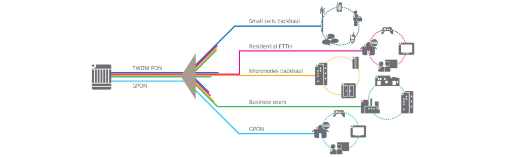
Print.
  • TWDM-PON can accelerate the process of bringing more bandwidth to more users. Increasingly, operators are deploying deep fiber micro-nodes so that they can quickly and cost-efficiently cover more users. These deployments demand high-capacity backhaul. As operators add more micro-nodes, the need for TWDM will surge.
  • TWDM-PON enables operators to add flexibility to the customer experience by letting users share the unused common part of bandwidth capacity. For example, an operator could guarantee that 1 Gbps of bandwidth will always be available to all users. Using TWDM-PON, it could allow users to burst above their assigned bandwidth up to 10Gbps to accelerate actions such as downloading HD movies or backing up data to cloud storage.
  • With TWDM, different wavelengths can be assigned to different operators. This flexibility will facilitate co-investment in common infrastructure, encourage investment and promote sharing of cost and risk.
Get More Value from Existing Fiber

One of the key requirements for NG-PON2 is to preserve operators’ current PON investments and allow them to reuse their most expensive component: the outside plant. TWDM-PON addresses this requirement in three key ways:

  1. GPON compatibility: TWDM-PON can coexist with, and expand on, current GPON deployments. This coexistence ensures that operators’ fiber investments will keep providing value in the long term.
  2. Zero outside plant impact: TWDM-PON typically has no cost or operational impact on existing passive components, including the outside plant. As part of this no-impact approach, TWDM-PON uses the same splitters to simplify fiber management, facilitate tuning and maximize compatibility with network components and end-user equipment.
  3. Easy introduction: TWDM-PON can be introduced smoothly and gradually into existing Fiber To The X (FTTX) deployments. Although integrated multi-wavelength solutions are feasible, some operators may find it easier to start with one wavelength and add more as bandwidth demand grows. Upgrades can be introduced on a fiber-by-fiber basis. They are as simple as adding and configuring new cards at the central office.
Reduce Cost and Risk

TWDM-PON promises to reduce cost and risk by promoting efficient operations. Specifically, it supports wavelength management techniques that can allow operators to move end users from one wavelength to another to rebalance bandwidth, reconnect users to other operators, or decrease downtime during software upgrades. These techniques can help operators forgo expensive truck rolls and in-field fiber reconnections in favor of efficiently reassigning users to specific wavelengths from the central office.

Co-investment offers additional opportunities to reduce cost and risk. TWDM-PON brings successful co-investment within reach by providing an environment in which several operators can effectively share a common fiber infrastructure. With TWDM-PON, individual wavelengths can be associated with and controlled by different operators. Each co-investor benefits from lower capital and maintenance costs, added flexibility to support new services, and new opportunities to establish partnerships and business models.

Open, government-owned fiber networks can also provide opportunities to reduce cost and risk. TWDM-PON permits each operator to use one (or more) wavelengths on the common PON, deployed on either common or separate central office equipment. With their own wavelengths, operators gain the flexibility and independence to offer, manage and upgrade quality of service according to their business priorities.

Technical Enablers and Optimization

Operators need efficient solutions that can help them capitalize on the potential and benefits of TWDM-PON. Areas requiring technical enablers and optimization include wavelength tuning, optical signal amplification and scalability.

Wavelength tuning

To simplify operations, all TWDM ONTs must be colorless. The ONT transceiver must be able to tune to the correct wavelengths in upstream and downstream during end-user provisioning.

Operators can use a variety of techniques to control the wavelength in the upstream direction from the ONT to the OLT. Temperature is the primary parameter of control. For example, thermo-electric controlled lasers can use heating and cooling to accurately set the wavelength. These lasers are available today and can be used in the ONT, but they are expensive.

A heat-only laser could provide a more cost-effective and power-efficient alternative for addressing the needs of the mass market. However, a heat-only approach can only set the laser to wavelengths that correspond to the ambient temperature or above—never below. Therefore, a cyclic Wavelength Multiplexer (WM) must be used at the OLT to route sets of wavelengths, rather than individual wavelengths, to each OLT port. In this way, the laser can be heated above ambient temperature until its wavelength is part of a given wavelength set associated with the destination OLT port. The wavelength sets are analogous to the sets of piano notes with the same name (i.e. “C”, “D”, “E” etc.) and which repeat cyclically at every octave. This results in a simple and low-cost tuning scheme.

In the long-term, it is hoped that photonic integrated circuits will provide other economical solutions to wavelength control.

In the downstream direction, thermo-controlled thin-film filters can be integrated into the ONT receiver to allow tuning. Photonic integrated circuits may provide a future solution.

At the OLT side, thermoelectric-controlled lasers can accurately hold the downstream wavelengths at the correct wavelength. The upstream wavelengths are routed to the correct OLT receiver by way of a WM, using either Thin-Film Filter (TFF) technology or Arrayed Waveguide Gratings (AWGs).

Optical signal amplification

To transmit higher bit rates with a low error rate, it is necessary to improve the sensitivity of the receivers or increase the level of the received signal. Amplification is needed to transmit these higher-rate optical signals through existing fiber networks, which have a fixed attenuation. The need for amplification is even greater given that NG-PON2 is simultaneously targeting an increased split ratio, greater fiber distances and higher speeds.

Some amplification technologies can be used in both the upstream and downstream directions. These include semiconductor optical amplifiers (SOA) and Erbium Doped Fiber Amplifiers (EDFA). With SOAs, the optimal amplifier location is immediately after the laser in the downstream direction and before the wavelength demux in the upstream direction. All of these components are typically located in the central office.

Scaling and evolution

Operators will need to choose the equipment growth and fiber evolution strategy that best addresses their business needs. For many, the key decision will be whether to adopt a pay-as-you-grow strategy with modular optical components or deploy a fully integrated solution in anticipation of future demand. Others will need to decide whether it makes more business and operational sense to go it alone or embrace a co-investment or network sharing strategy.

Most technical issues can be solved with solutions and advice from knowledgeable vendors. Vendors can also help with business issues, but operators will ultimately need to choose the strategies that best align with their business goals.

Unlock network potential with TWDM

Today’s GPON-based networks are bringing fundamental change to many different industry sectors. However, GPON is tapping a fraction of fiber’s potential. New technologies like TWDM will unlock this potential by adding capacity and flexibility. These improvements will help operators generate more revenue by converging multiple services onto one fiber. They will help operators lower cost by increasing operational efficiency and providing access to viable co-investment options. TWDM will also help operators preserve their existing fiber investments: The upgrade path to TWDM uses the same fiber and passive components as current GPON networks and simply overlays new active components.


From Alcatel-Lucent

Talking about the comparison between CWDM and DWDM

CWDM, just as DWDM, use multiple light wavelengths to transmit signals over a single optical fiber. However, there are still some differences betwwen the two techologies in many ways.

CWDM uses a 20-nm wavelength spacing that is much wider than the 0.4 nm for DWDM. The wider wavelength spacing in CWDM means lower product development costs. This is one reason why CWDM is less costly than DWDM.

Most CWDM devices operate in the 1470-nm to 1610-nm range. The frequency grid for DWDM and the wavelength grid for CWDM systems are defined by the international telecommunication union (ITU) standard G.694.1 and G.694.2, respectively.

CWDM provides a maximum of 8 lambadas between two CWDM multiplexers over a single fiber pair as compared to DWDM Multiplexers, which support up to 32 lambdas (based on 0.8-nm or 100-GHz wavelength spacing) over a single fiber pair. some long-haul DWDM systems can support up to 160 lambdas per fiber pair.

Each CWDM channels uses a specialized gigabit interface converter (GBIC) or small form-factor pluggable (SFP) transceivers are commonly known as colored GBIC and SFP. Each CWDM channels uses a different “color” GBIC or SFP because each lambda represents a different color in the spectrum. In this case, the native GBIC or SFP in the client devices are substituted with a colored GBIC or SFP.

CWDM multiplexers are usually passive (i.e, not powered) devices containing a very accurate prism to multiplex eight separate wavelengths of light along a single fiber pair. And passive CWDM devices cannot generate or repeat optical signals.

No amplification is possible with CWDM because CWDM uses wavelengths that cannot be amplified with EDFA amplifiers. Therefore, the maximum distance for a CWDM link is approximately 100 km.

The Cisco ONS 15501 EDFA, which has a wavelength range of 1530 nm to 1563 nm, can only amplify two signals (1530 nm and 1550 nm) out of the eight signals that are multiplexed onto the fiber pair.

CWDM provides an alternative solution to DWDM for low-latency and high-bandwidth requirements associated with synchronous replication application. However, DWDM is more scalable than CWDM. DWDM also has a longer distance capacity than CWDM because DWDM can be amplified. The main benefit of CWDM is its low cost. It is a cheaper solution than DWDM. In other words, CWDM is optimized for cost, while DWDM is optimized for bandwidth. For enterprises that have access to dark fiber and have only limited scalability requirement, CWDM is a relatively inexpensive way to achieve low-latency and high-bandwidth interconnections between DCs. The CWDM implementation also results in less complex installation, configuration, and operation as compared to DWDM.

CWDM can be deployed in point-to-point, linear, or fiber protected ring topologies, It is limited to a distance of up to 120 km for Gigabit Ethernet and 100 km for 2-G FC in a point -to-point topology. It is typically used only for extension of the FC fabric in a metro or campus application. As CWDM carries only eight lambdas on a single fiber pair, there are limits to the number of possible drops and the number of sites that can be interconnected. A ring or linear topology reduces the distance depending on the number of OADMs traversed by the CWDM channels because each CWDM OADM introduces additional power loss in the network.

CWDM OADM

CWDM can also be used to enable multiple ISL connections between the switches over a single fiber since it requires less fiber for interconnecting two metro sites. The same benefit applies to port channel implementation between the switches.

In short, DWDM is a solution that provides a higher number of connections and longer reach, or extension, at a much higher cost while CWDM is a more cost-effective solution for metro or campus solutions where the distance is limited.

If you have any questions about CWDM and DWDM technology, welcome to visit our online store. http://www.fiberstore.com/

Article Source: http://www.fiber-optical-networking.com/


CWDM Technology VS DWDM Technology

WDM is a technology that is achieved using a multiplexer to combine wavelengths traveling through different fibers into a single fiber. The space between the individual wavelengths transmitted through the same fiber are the basis for differentiating the CWDM and DWDM.

CWDM- Coarse wavelength division multiplexing. WDM systems with fewer than eight active wavelengths per fiber. DWDM – Dense wavelength division multiplexing. WDM systems with more than eight active wavelengths per fiber.

CWDM is defined by wavelengths. DWDM is defined in terms of frequencies. DWDM’s tighter wavelength spacing fit more channels onto a single fiber, but cost more to implement and operate. CWDM match the basic capacities of DWDM but at lower capacity and lower cost. CWDM enable carriers to respond flexibly to divers customers needs in metropolitan regions where fiber may be at a premium. The point and purpose of CWDM is short-range communications. It uses wide-range frequencies and spreads wavelengths far apart from each other. DWDM is designed for long-haul transmission where wavelengths are packed tightly together. Vendors have found various techniques for cramming 32, 64, or 128 wavelengths into a fiber. DWDM system is boosted by Erbium-Doped Fiber Amplifier, so that to work over thousands of kilometers for high-speed communications.

Hardware Cost
The cost difference between CWDM and DWDM systems can be attributed to hardware and operational costs. Despite the superiority in terms of cost of DWDM laser with respect to the CWDM DFB laser chilled provide cost effective solutions for long haul and metro rings large capacity demanding. In both applications, the cost of DWDM system is set off by the large number of customers who use this system. Except for encapsulation, the DWDM laser for stabilizing the temperature with a cooler and a thermistor, it is more costly than an uncooled laser coaxial CWDM.

Power Consumption
The energy requirements for DWDM are significantly higher. For example:DWDM laser temperature stabilized through coolers integrated modules encapsulation, These devices together with the associated PIN and the control circuit consumes approximately 4 W of power per wavelength monitor. However, an uncooled CWDM laser transmitter consumers about 0.5w. The transmitter of 8 channel CWDM system consume about 4W of power, while the same functionality in a DWDM system can consume up to 30W. As the number of wavelengths in DWDM systems with increased transmission speed, power and thermal management associated with them becomes a critical issue for the designers.

Because DWDM doesn’t span long distance as its light signal isn’t amplified, which keeps costs down but also limits maximum propagation distances. Manufacturers may cite working ranges of 50 to 80 kilometers, and by signal amplifiers to achieve 160 kilometer. CWDM supports fewer channels and that may be adequate for carrier who would like to start small but expand later when demand increases.

CWDM DWDM Networking Solutions

Wavelength division multiplexing is a cost effective and efficient way for expanding the fiber optic transmission capacity, because it allows using current electronics and current fibers and simply shares fibers by transmitting different channels at different color (wavelength) of light.

Wavelength Division Multiplexing, WDM is a technique that multiplexing several signals over a single fiber optic cables by optical carriers of different wavelength, using light from a laser or a LED. According to the number of wavelengths it supports, there are Coarse Wavelength Division Multiplexing (CWDM) and Dense Wavelength Division Multiplexing (DWDM).

CWDM was introduced as a low-cost approach to increasing bandwidth utilization of the fiber infrastructure. By using several wavelengths/colors of the light, 18 channels are viable and defined in the ITU-T standard G.694.2. CWDM systems typically provide 8 wavelengths, separated by 20nm, from 1470nm to 1610nm.

Benefits of CWDM
Passive equipment that uses no electrical power
Extended Temperature Range (0-70C)
Much lower cost per channel than DWDM
Scalability to grow fiber capacity with little or no increased cost
Protocol Transparent
Simple to install and use

Drawbacks of CWDM
16 channels may not be enough
Passive equipment offers no management capacities

DWDM packing WDM channels denser than in CWDM systems, 100 GHz spacing (approx. 0.8nm), more channels and higher capacity can be achieved using DWDM. IUT-T recommendation G.694.1 defines the DWDM channels spectrum. DWDM comes in two different versions: an active solution and a passive solution. An active solution is going to require wavelength management and it a good fit for applications involving more than 32 lines over the same fiber. In most cases, passive DWDM is looked at as a more realistic alternative to active DWDM.

Benefits of DWDM
Up to 32 channels can be done passively
Up to 160 channels with an active solution
Active solutions typically involve optical amplifiers to achieve longer distances

Drawbacks of DWDM
DWDM is very expensive
Active solutions require a lot of set-up and maintenance expense
“Passive” DWDM solution still requires power

Optical Add/Drop Multiplexing (OADM)
By optical add/drop multiplexing techniques, wavelength channels may be added and dropped at intermediate nodes using passive optical components only. Optical Add/Drop Multiplexers are used in WDM Systems for multiplexing and routing fiber optic signals. They can multiplex several low-bandwidth streams of data into a single light beam, and simultaneously, it can drop or remove other low-bandwidth signals from the stream of data and direct them to other network routers. There are CWDM OADM and DWDM OADM.

FiberStore offer a wide range of WDM optical networking products that allow transport of any mix of service from 2Mbps up to 200Gbps. Our highly reliable WDM/CWDM/DWDM products include CWDM multiplexers and demultiplexer, DWDM Multiplexers and demultiplexers, CWDM & DWDM Optical Add-drop Multiplexer, Filter WDM modules, CATV amplifier, OEO converters as well as many other most demanding CWDM DWDM networking infrastructure equipment.

WDM Technology

After languishing for many years as an interesting technology without a cost-effective application, wavelength-division multiplexing started playing a major role in telecommunications networks in the early 1990s, This resulted from the surge in demand for high-capacity links and the limitation of the installed fiber plant in handling high-rate optical signals over any substantial distance.

This limitation led to a rapid capacity exhaustion of long-haul fiber networks.
While installing an optical fiber cable plant is both expensive and extremely time consuming, expanding the capacity of an installed network is economically attractive. Tradition carries upgraded their link capacity by increasing the transmission rate. This worked well initially, with speeds eventually reaching 2.5 Gb/s. However, when going to the next multiplexing level of 10Gb/s, people starts to encounter the effects that can seriously degrade WDM network performance such as the dispersion, reflections, scattering, etc.

New fiber designs, special dispersion-compensation techniques, and optical isolators can mitigate these limitations, and newly installed links are operating very well as 10Gb/s per wavelength.

However, a large portion of the older installed fiber base is limited to OC-48 rates (2.5Gb/s) at a given wavelength. Thus, a great interest has been established in using WDM, not only for older links but also to have a very high capacity new links.

For a typical WDM link. At the transmitting end, there are several independently modulated light sources, each emitting signals at a unique wavelength. Here a multiplexer is needed to combine these optical outputs into a continuous spectrum of signals and couple them onto a single fiber. At the receiving end, a demultiplexer is required to separate the optical signals into appropriate detection channels for signal processing. At the transmitter, the basic design challenge is to have the multiplexer provide a low-loss path from each optical source to the multiplexer output. Since the optical signals that are combined generally do not emit any significant amount of optical power outside of the designated channel spectral width, interchannel cross-talk factors are relatively unimportant at the transmitting end.

WDM Multiplexers
Wavelength multiplexers are specialized devices that combine a number of optical streams at distinct wavelengths and launch all their powers in parallel into a single fiber channel. This
combination need not be uniform for all wavelengths; that is. One may want to combine 50% of the power from on wavelength, 75% from another source, and 100% from other wavelengths. However, for WDM applications it is usually desirable that the multiplexers combine the optical powers from multiple wavelengths onto a single fiber with little loss. Wavelength demultiplexers divide a composite multichannel optical signal into different output fibers according to wavelength without splitting loss. This section describes a phased-array-based WDM multiplexer and a fiber-grating multiplexer as examples of such components.