Cisco 3650 vs. 3850 Catalyst Switches

Cisco Catalyst 3650 and 3850 series switches are enterprise class stackable switches. Cisco Catalyst 3650 series was unveiled in 2013 which designed to converge wired and wireless networking. Just in the same year, Cisco launched its first flagship Catalyst 3850 series switches . That provide a converged wired and wireless platform as well. With they have many things in common, many people confused about them and found it hard to decide which one to buy. This article would introduce Cisco 3650 vs. 3850 series switch as well as Cisco 3650 vs. 3850 differences.

Cisco Catalyst 3650 Series Switch

There are 21 Cisco 3650 Series Switch models in total. All Cisco Catalyst 3650 Series Switches have fixed, built-in uplink ports. The Catalyst 3650 features line rate 24 and 48 Gigabit Ethernet ports and an integrated wireless controller. It can be stacked in groups of nine switches for support of up to 25 access points and 1,000 clients at 40Gbps. The uplink ports of all switch models can be divided into the following five types:

  • Four Gigabit Ethernet with Small Form-Factor Pluggable (SFP Transceiver)
  • Two 10 Gigabit Ethernet with SFP+ and two 10 Gigabit Ethernet with SFP or four Gigabit Ethernet with SFP
  • Four 10 Gigabit Ethernet with SFP+ or four Gigabit Ethernet with SFP
  • Eight 10 Gigabit Ethernet with SFP+ or eight Gigabit Ethernet with SFP
  • Two 40 Gigabit Ethernet with QSFP+

Product Image of Cisco Catalyst 3650 Series Switches

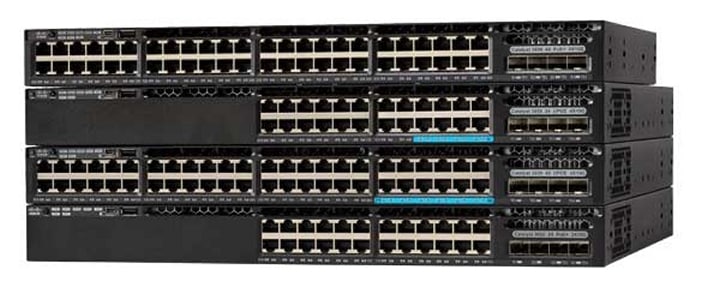
Figure1: Cisco 3650 PoE+ Switch(Resource: www.Cisco.com)

Cisco Catalyst 3850 Series Switches

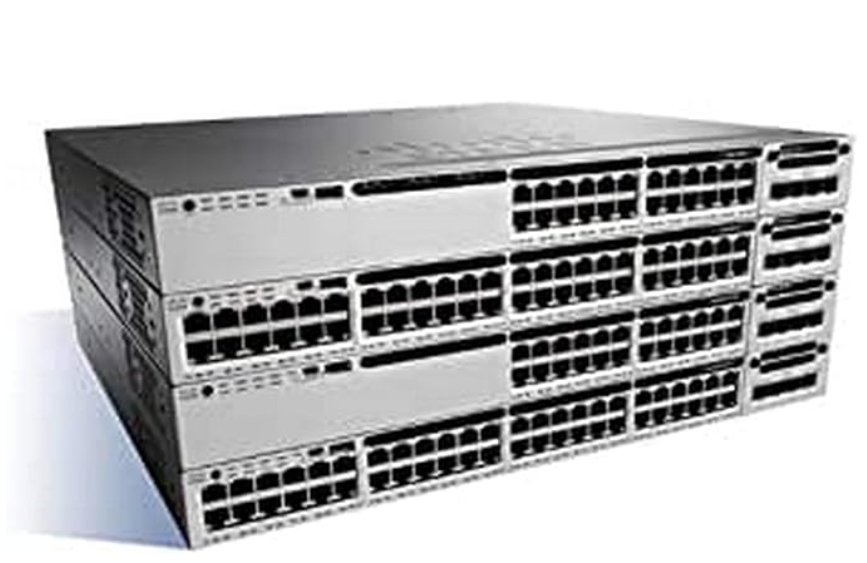
The Cisco Catalyst 3850 Series Switches are modular and field-replaceable network modules, which has RJ45 and fiber-based downlink interfaces, and redundant fans and power supplies. It fully supports IEEE 802.3 at Power over Ethernet Plus (PoE+). Compared with 3650 Series Switches, they have less switch modules—14 switch modules. Besides, they are stackable 3K switches, which can fully meet your requirement for evolving business. Some main features of Cisco 3850 are just listed in the following:

  • Functionality added traffic aggregation. All Unified Access intelligent services can be persevered and delivered across the entire network from the access layer to the aggregation layer.
  • Long distance transmission. The 3850 switches can be used to connect branch offices and small campus buildings. The fiber connections can support up to 80 km of physical distance.

相关图像、图表或屏幕截图

Figure2: Cisco 3850 PoE+ Switch(Resource: www.Cisco.com)

  • High compatibility. The 3850 switches support a variety of optical modules and connectors, therefore allowing many deployment options.
  • Enhanced security. It comes with native TrustSec functionality such as Security Group Tag (SGT) so that you have it enabled everywhere—from access to aggregation. Also, fiber connections provide strong physical security.
Cisco 3650 vs. 3850 Switches: Differences
—Flexibility

The flexibility of the 3850s is greater than the 3650s, because they are stacking and optional stacking switches respectively. The 3850s can do power stacking, that is an exclusive feature compared to the 3650s. Stacking is built in, and the short stacking cables are included. Larger stacks might require the longer stacking cables, that is a potential downside.

3650s can do stacking as well, but you need to buy the modules separately (and they are like $1,000 a pop list price), which adds up quickly.

—Power

The 3850s is the more powerful device than the 3650s, which featured as the great horsepower. Besides, as we mentioned before, the 3850s can do power stacking while the 3650s cannot.

—Capacity

Compared with the 3650s series switches, the 3850s series switches have higher capacity. The maximum switching capacity of the 3850s switches can arrive at 1280 Gbps on 48-port 10 Gigabit Ethernet SFP+ model while the 3650s switches at 472 Gbps on 48-port Multigigabit models.

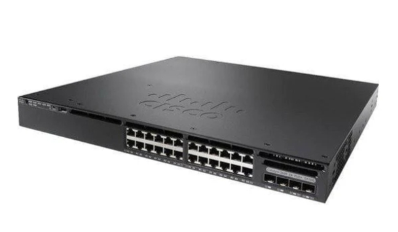
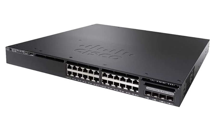
Figure3: Cisco 3650 24Port PoE+ switch(Resource: www.Cisco.com)

—Price

There are only slight differences between the two switches in terms of price. Just take the 24-port switches of two different series for example, you can see the differences more clearly by clicking the following link:

Cisco-WS-C3850-24P-S:

Cisco-WS-C3650-24PD-S:

Conclusion

This article chiefly discussed the Cisco 3650 vs. 3850 series switches as well as their differences. How to choose? They are both great switches. It depends on what you really want to do and what you want out of your switches, and what your budget is. Besides, if you are looking for the compatible optical modules for those two switches, you can take FS.COM a try. We offer large and in-stock Cisco SFP, SFP+, 40G QSFP+ and 100G QSFP28 optical transceivers with high quality but low cost. For more details, please visit www.fs.com.

Edgeswitch vs. Unifi switch

Recently, Ubiquiti Network Switch is of prevalence for building and expanding home network. EdgeSwitch and Unifi Switch are two main switch series of the Ubiquiti Network Switch. For years, the EdgeSwitch and Unifi Switch are featured as cost-effective, robust performance, and this is why many people have special favor on them. For they both a good choice for growing networks, it is necessary to make clear their differences and decide which one to choose. In this article, we will mainly introduce the EdgeSwitch vs Unifi Switch, similarities and differences as well as compatible SFP transceivers for them.

Figure 1: This picture shows Unifi Switch US-8-150W(Resource: www.Ubiquiti.com)

Introduction to Unifi Switch

The Unifi Switches provide 8, 16, 24, or 48 PoE Gigabit Ethernet ports to satisfy different requirement for expanding Gigabit Ethernet network and making your network cabling looks neat. They support IEEE 802.3af and IEEE 802.3at. And the operation is rather easy, you can directly connect your switch to a storage server through two SFP ports on each switch. The transmission rate can be up to 1 Gbps. For longer distance and higher bandwidth, you can use Unifi Switch with 48-port which additional added two more SFP+ port.

Information About EdgeSwitch

As same as Unifi Switch, the EdgeSwitch has the same PoE Gigabit Ethernet ports and IEEE protocols. The most distinctive feature of Edgeswitch is that offers an extensive suite of advanced Layer-2 switching features and protocols, and also provides Layer-3 routing capability. There are 6 EdgeSwitch models, the accurate ports’ number are clearly shown in the below chart. You can use ES-8-150W, ES-16-150W and ES-24-250W as well as ES-24-500W switch models to achieve 1G Ethernet network connectivity. SFP+ transceivers, you can choose ES-48-500W, ES-48-750W to arrive 10 Gbps connection.

Figure 2: This picture shows Unifi EdgeSwitch(Resource: www.Ubiquiti.com)

Similarities Between EdgeSwitch vs Unifi Switch

Both Unifi Switch and EdgeSwitch have 8, 16, 24, or 48 PoE Gigabit Ethernet ports.

—Switch models

As for edgeswitch vs unifi switch, the two switches basically share the identical switch type (switch ports and Watts), the only difference lies in the EdgeSwitch does not have one with 8 ports for 60W.

—Protocols

The Unifi Switch and EdgeSwitch both support IEEE 802.3af and IEEE 802.3at.

—Supporting Gigabit Ethernet

They both support 1G and 10G Ethernet connections and have both SFP and SFP+ ports.

Differences Between EdgeSwitch vs Unifi Switch

—Color
The EdgeSwitch is black while the Unifi Switch is silver.

—Management

The Unifi Switch can only be managed through the UniFi controller while the EdgeSwitch can only be managed through it’s CLI or web interface.

—Routing protocols

The EdgeSwitches only support static routing, and there are no routing protocols implemented while Unifi Switches don’t support routing at all.

FS.COM’s Compatible SFP Module for EdgeSwitch vs Unifi Switch:

Multi-mode and single mode SFP models are available for Unifi and Edge switch. FS.COM is a leading manufacturer and supplier of fiber optic subsystems, components and solutions. Our optical modules are well known as the superior quality and high compatibility. Besides, all of our products are tested and 100% compatible with major brands, such as Cisco, Juniper, Brocade, Arista, etc. You can rest assured to use them. For this Unifi and Edge switch, we offer the following compatible SFP module:

1000Base-LX: SFP1G-LX-31 1310nm (Single Mode SFPs).

1000Base-SX: SFP-1G85-5M (multi-mode).

1000Base-T: SFP-GB-GE-T Module.

Arista Networks SFP-1G-LX Compatible 1000BASE-LX SFP 1310nm 10km DOM Duplex LC SMF Transceiver Module

Figure 3: This picture shows FS SFP Transceiver(Resource: fs.com/uk)

Conclusion

Ubiquiti Network Switch seems to be an irresistible trend for home network connectivity. Through this passage, we learned that EdgeSwitch vs Unifi switch are different in color, management and routing protocols. If you are looking for compatible SFP transceivers for those two kinds of switches, you can give FS.COM a try. In addition to SFP transceivers, we still offer many other optical products, such as patch cables, SFP+, QSFP and QSFP28 optical modules, network cables, switches, etc. If you are interested, you can visit www.fs.com.

Related Article:
Gigabit Switch: Ethernet Switches Recommendations
Managed vs Unmanaged Switch: Which One Can Satisfy Your Real Need?

Connectivity Solutions for Parallel to Duplex Optics

Since we have discussed connectivity solutions for two duplex optics or two parallel optics in the last post (see previous post: Connectivity Solutions for Duplex and Parallel Optics), the connectivity solutions for parallel to duplex optics will be discussed in this article, including 8-fiber to 2-fiber, and 20-fiber to 2-fiber.

Parallel to Duplex Direct Connectivity

When directly connecting one 8-fiber transceiver to four duplex transceivers, an 8-fiber MTP to duplex LC harness cable is needed. The harness will have four LC duplex connectors and the fibers will be paired in a specific way, assuring the proper polarity is maintained. This solution is suggested only for short distance within a given row or in the same rack/cabinet.

8-fiber to 2-fiber direct connectivity

Figure 1: 8-fiber to 2-fiber direct connectivity

Parallel to Duplex Interconnect

This is an 8-fiber to 2-fiber interconnect. The solution in figure 2 allows for patching on both ends of the fiber optic link. The devices used in this link are recorded in the table below figure 2.

8-fiber to 2-fiber interconnect

Figure 2: 8-fiber to 2-fiber interconnect

Item Description
1 8 fibers MTP trunk cable (not pinned to pinned)
2 96 fibers MTP adapter panel (8 ports)
3 8 fibers MTP trunk cable (not pinned)
4 MTP-8 to duplex LC breakout module (pinned)
5 LC to LC duplex patch cable (SMF/MMF)

Figure 3 is also an interconnect for 8-fiber parallel QSFP+ to 2-fiber SFP+. This solution is an easy way for migration from 2-fiber to 8-fiber, but it has disadvantage that the flexibility of the SFP+ end is lacked because the SFP+ ports have to be located on the same chassis.

8-fiber to 2-fiber interconnect

Figure 3: 8-fiber to 2-fiber interconnect

Item Description
1 8 fibers MTP trunk cable (not pinned to pinned)
2 96 fibers MTP adapter panel (8 ports)
3 8 fibers MTP trunk cable (not pinned)
4 8 fibers MTP (pinned) to duplex 4 x LC harness cable

Figure 4 shows how to take a 20-fiber CFP and break it out to ten 2-fiber SFP+ transceivers. The breakout modules divide the twenty fibers into three groups, and ten LC duplex cables are used to accomplish the connectivity to SFP+ modules.

20-fiber to 2-fiber interconnect

Figure 4: 20-fiber to 2-fiber interconnect

Item Description
1 1×3 MTP breakout harness cable(24-fiber MTP to three 8-fiber MTP) (not pinned)
2 MTP-8 to duplex LC breakout module (pinned)
3 LC to LC duplex cable (SMF/MMF)
Parallel to Duplex Cross-Connect

There are two cross-connect solutions for 8-fiber parallel to 2-fiber duplex. The main difference for figure 5 and 6 is on the QSFP+ side. The second cross-connect is better for a greater distance between distribution areas where the trunk cables need to be protected from damage in a tray.

8-fiber to 2-fiber cross-connect (1)

Figure 5: 8-fiber to 2-fiber cross-connect (1)

Item Description
1 8 fibers MTP trunk cable (not pinned)
2 MTP-8 to duplex LC breakout module (pinned)
3 LC to LC duplex cable (SMF/MMF)

8-fiber to 2-fiber cross-connect (2)

Figure 6: 8-fiber to 2-fiber cross-connect (2)

Item Description
1 8 fibers MTP trunk cable (not pinned to pinned)
2 96 fibers MTP adapter panel (8 ports)
3 8 fiber MTP trunk cable (not pinned)
4 MTP-8 to duplex LC breakout module (pinned)
5 LC to LC duplex cable (SMF/MMF)
Conclusion

These solutions are simple explanations to duplex and parallel optical links. It seems that the difference between each solution is not that significant in plain drawing, but actually the requirements for components are essential to an efficient fiber optic network infrastructure in different situations. Whether it is a narrow-space data center or a long-haul distribution network that will mostly determine the cabling structure and the products used.

Which Fiber Loopback Should I Use for My Transceiver?

In telecommunication, fiber loopback is a hardware designed to provide a media of return patch for a fiber optic signal, which is typically used for fiber optic testing or network restorations. When we need to know whether our fiber optic transceiver is working perfectly, we can use a fiber loopback cable as an economic way to check and ensure it. Basically, the loopback aids in debugging the physical connection problem of the transceiver by directly routing the laser signal from the transmitter port back to the receiver port. Since fiber optic transceivers have different interface types and connect different types of cables, it is not that simple to choose a right loopback for our transceiver. This post will be a guide on how to choose a right loopback cable for specific transceiver module.

Fiber Loopback Types and Configurations

Before deciding which loopback cable to use, we should firstly know the structure and classification of fiber loopback cable. Generally, a fiber loopback is a simplex fiber optic cable terminated with two connectors on each end, forming a loop. Some vendors provide improved structure with a black enclosure to protect the optical cable. This designing is more compact in size and stronger in use. Based on the fiber type used, there is single-mode loopback and multimode loopback, available for different polishing types. According to the optical connector type of the loopback, fiber loopback cables can be divided to LC, SC, FC, ST, MTP/MPO, E2000, etc. In testing fiber optic transceiver modules, the most commonly used are LC, SC and MTP/MPO loopback cables.

lc&sc loopback cable
Figure 1: LC & SC Loopback Cable

The LC and SC loopbacks are made with simplex fiber cable and common connectors; it’s not difficult to understand their configurations. As for the MTP/MPO loopback, it is mainly used for testing parallel optics, such as 40G and 100G transceivers. Its configuration varies since the fiber count is not always the same in different applications.

8 Fibers MTP/MPO Loopback Cable Configuration

In a 8 fibers MTP/MPO loopback, eight fibers are aligned on two sides of the connector, leaving the central four channels empty. And the fibers adopt a straight configuration of 1-12, 2-11, 5-8, 6-7. The polarity channel alignment is illustrated in the following figure.

8 Fibers Loopback Polarity Channel Alignment
Figure 2: 8 Fibers Loopback Polarity Channel Alignment
12 Fibers MTP/MPO Loopback Cable Configuration

The only difference between the 12-fiber MTP loopback and the 8-fiber loopback is that the central four channels are not empty. Its alignment is 1-12, 2-11, 3-10, 4-9, 5-8, 6-7.

12 Fibers Loopback Polarity Channel Alignment
Figure 3: 12 Fibers Loopback Polarity Channel Alignment
24 Fibers MTP/MPO Loopback Cable Configuration

The 24 fibers MTP loopback also adopts type 1 polarity. Its alignment design is shown below.

24 Fibers Loopback Polarity Channel Alignment
Figure 4: 24 Fibers Loopback Polarity Channel Alignment
Which to Choose for a Specific Transceiver?

Considering the common features of the transceiver and the loopback, we should think about the connector type, polish type, and cable type when selecting a loopback for the transceiver. The selection guide for some mostly used transceiver modules is summarized in the following tables.

Table 1: Loopback choices for 10G SFP+ transceivers

Model Interface type Cable Type Suited Loopback
10GBASE-USR LC Duplex (PC) MMF

LC/UPC Duplex Multimode Fiber Loopback

10GBASE-SR LC Duplex (UPC) MMF
10GBASE-LR LC Duplex (UPC) MMF
10GBASE-ER LC Duplex (UPC) SMF

LC/UPC Duplex Single-mode Fiber Loopback

10GBASE-ZR LC Duplex (PC) SMF

Table 2: Loopback choices for 40G QSFP+ transceivers

Model Interface type Cable Type Suited Loopback
40GBASE-CSR4 MTP/MPO (UPC) MMF

8/12 Fibers MTP/UPC Multimode Fiber Loopback

40GBASE-SR4 MTP/MPO (UPC) MMF
40GBASE-PLRL4 MTP/MPO (APC) SMF

8/12 Fibers MTP/APC Single-mode Fiber Loopback

40GBASE-PLR4 MTP/MPO (APC) SMF
40GBASE-LR4 LC Duplex (PC) SMF

LC/UPC Duplex Single-mode Fiber Loopback

40GBASE-LR4L LC Duplex (UPC) SMF
40GBASE-ER4 LC Duplex (UPC) SMF
40GBASE-LX4 LC Duplex (UPC) MMF/SMF

LC/UPC Duplex Multimode/Single-mode Fiber Loopback

Table 3: Loopback choices for 100G QSFP28 transceivers

Model Interface type Cable Type Suited Loopback
100GBASE-SR4 MTP/MPO (UPC) MMF

8/12 Fibers MTP/UPC Multimode Fiber Loopback

100GBASE-PSM4 MTP/MPO (APC) SMF

8/12 Fibers MTP/APC Single-mode Fiber Loopback

100GBASE-LR4 LC Duplex (UPC) SMF

LC/UPC Duplex Single-mode Fiber Loopback

Table 4: Loopback choices for CFP transceivers

Model Interface type Cable Type Suited Loopback
40GBASE-SR4 CFP MPO/MTP (UPC) MMF

8/12 Fibers MTP/UPC Multimode Fiber Loopback

40GBASE-LR4 CFP SC Duplex (UPC) SMF

SC/UPC Duplex Single-mode Fiber Loopback

40GBASE-FR CFP SC Duplex (UPC) SMF
100GBASE-LR4 CFP SC Duplex(PC/UPC) SMF
100GBASE-ER4 CFP SC Duplex(PC/UPC) SMF
100GBASE-SR4 CFP MPO/MTP (UPC) MMF

24 Fibers MTP/UPC Multimode Fiber Loopback

Conclusion

This post discusses specific fiber loopback choices for some most commonly used fiber optic transceivers. For other transceiver modules that are not mentioned in this post, we can also know how to choose a suitable loopback for it by getting details about its interface type, physical contact and cable type.

MTP Specifications and Deployment for 40GBASE-PLRL4 QSFP+

Commonly, QSFP+ transceiver designed with LC interface works with single-mode fiber for long distance application, while QSFP+ transceiver with MTP/MPO interface is used over multimode fiber for short distance transmission. For instance, 40GBASE-ER4 QSFP+ is designed with LC duplex interface, and it supports maximum transmission length of 40 km over single-mode LC duplex fiber; 40GBASE-SR4 QSFP+ with MTP/MPO interface supports a transmission distance no more than 150m over multimode fiber. However, in order to meet user’s diverse needs in real applications, some 40G transceivers are designed not following this rule, like 40GBASE-PLRL4 (parallel LR4 Lite). This transceiver is with MTP/MPO interface design but is used over single mode fiber for long distance transmission. This article will introduce the MTP/MPO specifications for this transceiver and its deployment cases.

40GBASE-PLRL4 transceiver

MTP Specifications for 40GBASE-PLRL4 QSFP+

QSFP-40G-PLRL4 transceiver uses MTP-12 interface to achieve parallel transmission, supporting maximum data links up to 1.4 km. The cable type required for 40GBASE-PLRL4 is an APC (angle polished connector) single-mode MTP-12 cable. The cable is similar to the 40G-SR MTP or MPO, with the only change being the use of single-mode fiber. UPC (ultra-polished connector) is another type of connector for MTP-12 cables, but it is not suited for single-mode fiber in the market. APC is the only available type for single-mode MTP-12 fiber. The MTP-12 connector plugged into the QSFP-40G-PLRL4 transceiver carries the 40G signal over only 8 of the 12 fibers, remaining four fibers unused, and these four can optionally be not presented in the cable for an economic reason. The used 8 fibers are mapped as 4x10G Tx and Rx pairs. In addition, the MTP cables connected to QSFP-40G-PLRL4 transceiver can be either MTP trunk cables or MTP splitter cables.

Deployment of 40GBASE-PLRL4 QSFP+

The QSFP-40G-PLRL4 is optimized to guarantee interoperability with any IEEE 40GBASE-LR4 and 10GBASE-LR. So when the link for 40G network and 10G to 40G migration is less than 1.4 km, it will be very appropriate to use 40GBASE-PLRL4 QSFP+ transceiver with single-mode MTP cables.

In the first case, you can choose an MTP trunk cable together with the 40GBASE-PLRL4 QSFP+ module for direct 40G connection. The following picture shows two 40GBASE-PLRL4 QSFP+ transceivers connected by a single-mode 12-fiber MTP trunk cable.

40GBASE-PLRL4 QSFP+ for 40G connection

In the second case, you can simply use an 8-fiber MTP to 4xLC duplex harness cable with one 40GBASE-PLRL4 QSFP+ and four 10GBASE-LR SFP+ to achieve 10G to 40G.

40GBASE-PLRL4 QSFP+ for 10G to 40G migration

You can see in the above two cases, MTP cable plays an important role and due to the special requirements of 40GBASE-PLRL4 for single-mode MTP fiber, it is necessary to choose the right MTP products connected to this 40G QSFP+.

Conclusion

40GBASE-PLRL4 QSFP+ module has special interface design which can be only compatible with single-mode MTP connector. During the deployment of 40GBASE-PLRL4 QSFP+ module, selecting proper MTP assemblies are essential to successfully accomplish the link. FS.COM is a professional fiber optic transceiver vendor and MTP product manufacturer, supplying compatible 40GBASE-PLRL4 QSFP+ transceiver of different brands, such as Cisco, Arista, Brocade, Huawei, etc. Also, other customized compatible brands are available for your requirements. MTP cables and assemblies are available for same-day shipping at low prices, including customized 8 fibers MTP/MPO trunk cable. You will be surprised to see how many kinds of network devices FS.COM can offer and you will get more than cost-effective products but also impressive service.