The Application of Fiber to the Desk (FTTD)

As communication technology develops rapidly, the demand for higher bandwidth is increasing. To solve this problem, optical cable is widely used as the backbone of communications network cabling, especially in big data center. In recent years, projects like FTTH (Fiber to the Home) and FTTB (Fiber to the Building) are carried out to provide better services for customers. To future capitalize on the benefits of optical cable, Fiber to the Desk (FTTD) is recommended for enterprises, financial institutions and federal agencies, which need high security and high data transmission speed. This article will guide you to have a closer look at application of FTTD.

Overview

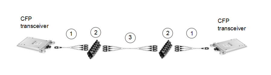
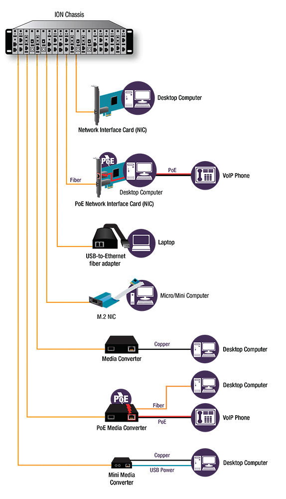
FTTD refers to the extension of the fiber optic infrastructure directly to user locations, just as the following figure show, optical cables are directly connected to desktops, laptops, or other communications equipment. FTTD can be used for virtual networks using thin clients and LAN networks with extended distances to workstations. It can satisfy the requirement for increasing bandwidth availability, moving large amounts of data at high transmission rates. In addition, it is able to bring service to locations where power is limited or unavailable as well as provide a more secure connection for organizations who are concerned about tapping or other security vulnerabilities.

FTTD

Advantages

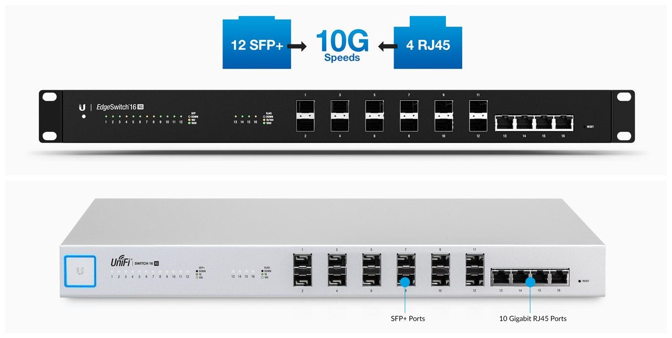
We know that RI45 Ethernet cable can also be used as transmission media. What makes optical cable superior to RJ45 Ethernet cable? This part will show you the advantages of using optical cable for FTTD project.

Security

Optical cable is immune to electromagnetic interference (EMI) and radio-frequency interference (RFI), so it is more difficult for hackers to tap on optical cable. Besides, optical cable uses light that is completely shielded, so hackers would have to physically splice into the line, which is difficult to do and easily detected. While RJ45 Ethernet cable emits electromagnetic signals which allows hackers to read data from nearby without physically touching the lines. In contrast, optical cable is a more secure option for applications concerned with data security.

Bandwidth And Distance

Optical cable is able to support higher data rates than any other cable type, with capacity to transmit up to 100 Gbit/s. As demand for higher bandwidth is ever-growing, optical cable has the absolute advantage. What’s more, connected with appropriate optics, the transmission distance of optical cable can reach dozen kilometers. Although higher grades of RJ45 Ethernet cables can transmit 10G data signals, they will only be able to do so over very short distances. Therefore, optical cable is the best choice for transporting higher speed and higher bandwidth signals over longer distances.

Lower Overall Cost

Optical cable used to be more expensive than RJ45 Ethernet cable. As demand has increased, manufacturing costs have dropped. Also, if properly designed, the FTTD project could be affordable. Apart from this, optical cable can ensure your network cabling can keep up with the growth in network traffic over time and upgrade your network to higher bandwidth in the future without recabling. Considering the cost of cabling, this can be a huge advantage. Though the initial cost of fiber equipment may be slightly higher than copper, the benefits realized can save organizations significant cost in the long term.

optical cable vs. RJ45 Ethernet cable

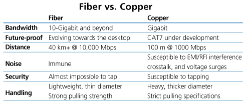
Optical cable Vs. RJ45 Ethernet cable

Conclusion

FTTD is a high-bandwidth solution that expands the traditional fiber backbone system by running fiber directly to desktops. FTTD is a horizontal wiring option that pushes the available bandwidth beyond 10G. It is an intriguing, underestimated and overlooked way to create a beneficial system that is expandable and performance-driven. The optical cable, fiber optic wall plate, PoE media converter and some other fiber optics used in FTTD are available in FS.COM. For more details, you can visit our site.

10GBASE-T Cabling Vs. 10G SFP+ Cabling in 2017

When it comes to 10G cabling network, we usually make a choice between 10GBASE-T cabling and 10G SFP+ cabling. In fact, many people still prefer 10G SFP+ cabling that uses SFP+ DAC cable, because they think it matches better for the requirements and emerging trends of today’s data center. Now the 10G network is quickly becoming mainstream, especially on consumer desktop systems. That means the cost of 10GBase-T switches will need to come down. Also, other “IOT” home components that decide to offer 10G will probably go for 10GBASE-T, such as game consoles, streaming boxes, etc. So, do you still recommend 10G SFP+ over 10GBASE-T nowadays for 10G cabling network deployment? This article will discuss this topic.

Vote for 10GBASE-T

  • The 10GBASE-T ports are physically smaller which is important for non-data center devices. They are also easier to use. You just plug in an ethernet cable and it works. No need to deal with optical transceiver compatibility and all of those problems.
  • The 10GBASE-T cabling is backwards compatible with 1G ports which will still be used for things like IPMI and other low bandwidth devices. You could just get one 10GBASE-T switch and connect up everything you have to it. Going with 10G SFP+ makes it difficult to find something that juggles enough of both kinds of ports for all of your 10G and 1G devices.

Vote for 10G SFP+

  • 10G SFP+ is better for future-proof cabling system. You can migrate to 40G QSFP+ smoothly and keep the existing cables. Even OM4 can do 100Gbps up to 150 meters. It is not known if Cat6a, Cat7 or even Cat8 will be able to pull off anything above 10Gb. And this will be stuck at 10G for quite some time.
  • 10G SFP+ interface that has been widely deployed for 10G ToR switches continues to use less power, typically less than 1 W per port. It also offers better latency—typically about 0.3 microseconds per link. While 10GBASE-T latency is about 2.6 microseconds per link due to more complex encoding schemes within the equipment.
  • 10GBASE-T switches are still expensive and there is a very limited choice of those that actually work. Also 10GBASE-T NICs add a premium over 10G SFP+. From a cost perspective, it is cheaper to go the 10G SFP+ cabling since you can find so many used 10G switches for deals, along with decent NICs. In addition, there is more support, driver wise for 10G SFP+ NICs than 10GBASE-T.

By comparison, we find that if flexibility and scalability are more important, 10GBASE-T cabling is a better option; but if power consumption and lower latency are critical, 10G SFP+ cabling may be more suitable. We also find that the cost of 10GBASE-T cabling is no longer in the ascendant. If 10GBASE-T want to acquire an absolute advantage, the primary goal now is to get 10GBASE-T cheaper and more power efficient and bring the cost way down so it can finally replace Gigabit as the next base level networking.

A Third Choice for 10G Cabling

If you do not have to choose vanilla or chocolate, you could have both 10GBASE-T and 10G SFP+ in the same switch, such as Ubiquiti EdgeSwitch 16 XG and UniFi Switch 16 XG. Both of them feature twelve 10G SFP+ ports and four RJ45 10GBASE-T ports to efficiently deliver and aggregate data at 10G speeds. But some people point out that the 10GBASE-T ports on the Ubiquiti switches actually don’t work reliably at 10Gbps speed. Therefore, before you buy it for those four RJ45 10GBASE-T ports, you have to make sure that they can work without issues. Here is a figure of them for you.

Ubiquiti EdgeSwitch 16 XG and UniFi Switch 16 XG

Conclusion

If you were building out a 10G cabling system from scratch today, which technology would you choose for your 10G network connectivity? Both the two cabling have their own advantages. And both of them occupy an important position in the future of network design and best practices. As for which one to choose, it all depends on your specific need. FS.COM can provide cost-effective solution for your 10G network deployment, such as Cat5e bulk cable, 10G SFP+ transceiver, 10G SFP+ DAC cable, 10GBASE-T SFP+ Transceiver and so on. For more details, please visit our site.

Related Article: 

Choose 10GBASE-T Copper Over SFP+ for 10G Ethernet

10GBASE-T vs SFP+, Which is Preferred for 10G Network Cabling

Connectivity Solutions for Parallel to Duplex Optics

Since we have discussed connectivity solutions for two duplex optics or two parallel optics in the last post (see previous post: Connectivity Solutions for Duplex and Parallel Optics), the connectivity solutions for parallel to duplex optics will be discussed in this article, including 8-fiber to 2-fiber, and 20-fiber to 2-fiber.

Parallel to Duplex Direct Connectivity

When directly connecting one 8-fiber transceiver to four duplex transceivers, an 8-fiber MTP to duplex LC harness cable is needed. The harness will have four LC duplex connectors and the fibers will be paired in a specific way, assuring the proper polarity is maintained. This solution is suggested only for short distance within a given row or in the same rack/cabinet.

8-fiber to 2-fiber direct connectivity

Figure 1: 8-fiber to 2-fiber direct connectivity

Parallel to Duplex Interconnect

This is an 8-fiber to 2-fiber interconnect. The solution in figure 2 allows for patching on both ends of the fiber optic link. The devices used in this link are recorded in the table below figure 2.

8-fiber to 2-fiber interconnect

Figure 2: 8-fiber to 2-fiber interconnect

Item Description
1 8 fibers MTP trunk cable (not pinned to pinned)
2 96 fibers MTP adapter panel (8 ports)
3 8 fibers MTP trunk cable (not pinned)
4 MTP-8 to duplex LC breakout module (pinned)
5 LC to LC duplex patch cable (SMF/MMF)

Figure 3 is also an interconnect for 8-fiber parallel QSFP+ to 2-fiber SFP+. This solution is an easy way for migration from 2-fiber to 8-fiber, but it has disadvantage that the flexibility of the SFP+ end is lacked because the SFP+ ports have to be located on the same chassis.

8-fiber to 2-fiber interconnect

Figure 3: 8-fiber to 2-fiber interconnect

Item Description
1 8 fibers MTP trunk cable (not pinned to pinned)
2 96 fibers MTP adapter panel (8 ports)
3 8 fibers MTP trunk cable (not pinned)
4 8 fibers MTP (pinned) to duplex 4 x LC harness cable

Figure 4 shows how to take a 20-fiber CFP and break it out to ten 2-fiber SFP+ transceivers. The breakout modules divide the twenty fibers into three groups, and ten LC duplex cables are used to accomplish the connectivity to SFP+ modules.

20-fiber to 2-fiber interconnect

Figure 4: 20-fiber to 2-fiber interconnect

Item Description
1 1×3 MTP breakout harness cable(24-fiber MTP to three 8-fiber MTP) (not pinned)
2 MTP-8 to duplex LC breakout module (pinned)
3 LC to LC duplex cable (SMF/MMF)
Parallel to Duplex Cross-Connect

There are two cross-connect solutions for 8-fiber parallel to 2-fiber duplex. The main difference for figure 5 and 6 is on the QSFP+ side. The second cross-connect is better for a greater distance between distribution areas where the trunk cables need to be protected from damage in a tray.

8-fiber to 2-fiber cross-connect (1)

Figure 5: 8-fiber to 2-fiber cross-connect (1)

Item Description
1 8 fibers MTP trunk cable (not pinned)
2 MTP-8 to duplex LC breakout module (pinned)
3 LC to LC duplex cable (SMF/MMF)

8-fiber to 2-fiber cross-connect (2)

Figure 6: 8-fiber to 2-fiber cross-connect (2)

Item Description
1 8 fibers MTP trunk cable (not pinned to pinned)
2 96 fibers MTP adapter panel (8 ports)
3 8 fiber MTP trunk cable (not pinned)
4 MTP-8 to duplex LC breakout module (pinned)
5 LC to LC duplex cable (SMF/MMF)
Conclusion

These solutions are simple explanations to duplex and parallel optical links. It seems that the difference between each solution is not that significant in plain drawing, but actually the requirements for components are essential to an efficient fiber optic network infrastructure in different situations. Whether it is a narrow-space data center or a long-haul distribution network that will mostly determine the cabling structure and the products used.

Connectivity Solutions for Duplex and Parallel Optics

In optical communication, duplex and parallel optical links are two of the most commonly deployed cabling structures. This post will discuss some specific connectivity solutions using 2-fiber duplex and 8-fiber/20-fiber parallel fiber optic modules.

Duplex and Parallel Optical Links

A duplex link is accomplished by using two fibers. The most commonly used connector is the duplex LC. The TIA standard defines two types of duplex fiber patch cables terminated with duplex LC connector to complete an end-to-end fiber duplex connection: A-to-A patch cable (a cross version) and A-to-B patch cable (a straight version). In this article the LC to LC duplex cables we use are all A-to-B patch cables. It means the optical signal will be transmitted on B connector and received on A connector.

two types of duplex-patch-cable

Figure 1: two types of fiber patch cables

A parallel link is accomplished by combining two or more channels. Parallel optical links can be achieved by using eight fibers (4 fibers for Tx and 4 fibers for Rx), twenty fibers (10 fibers for Tx and 10 fibers for Rx) or twenty-four fibers (12 fibers for Tx and 12 fibers for Rx). To accomplish an 8-fiber optical link, the standard cabling is a 12-fiber trunk with an MTP connector (12-fiber connector). It follows the Type B polarity scheme. The connector type and the alignment of the fibers is shown in figure 2.

8-fiber parllel system

Figure 2: parallel fiber (8-fiber) optic transmission

To accomplish a 20-fiber parallel optical link, a parallel 24-fiber MTP connector is used. Its fiber alignment and connector type is shown in figure 3.

20-fiber parallel system

Figure 3: parallel fiber (20-fiber) optic transmission
Duplex Fiber Optic Transmission Links (2-fiber to 2-fiber)

We will discuss the items required to connect two duplex transceivers in this part. These 2-fiber duplex protocols include but not limited to: 10GBASE-SR, 10GBASE-LR, 10GBASE-ER, 40GBASE-BiDi, 40GBASE-LR4, 40GBASE-LRL4, 40GBASE-UNIV, 40GBASE-FR, 100GBASE-LR4, 100GBASE-ER4, 100GBASE-CWDM4, 100GBASE-BiDi, 1GFC, 2GFC, 4GFC, 8GFC, 16GFC, 32GFC.

Duplex Direct Connectivity

When directly connecting two duplex SFP+ transceivers, an A-to-B type patch cable is required. This type of direct connectivity is suggested only to be used within a given row of racks/cabinets. Figure 4 shows two SFP+s connected by one LC to LC duplex patch cable.

2-fiber to 2-fiber direct connectivity Figure 4: 2-fiber to 2-fiber direct connectivity

Duplex Interconnect

The following figure is an interconnect for two duplex transceivers. An 8-fiber MTP trunk cable is deployed with 8-fiber MTP-LC breakout modules connected to the end of the trunk. It should be noted that the polarity has to be maintained during the transmission. And pinned connectors should be deployed with unpinned devices. Structured cabling allows for easier moves, adds, and changes (MACs). Figure 5 illustrates this solution.

2-fiber to 2-fiber interconnect (1)

Figure 5: 2-fiber to 2-fiber interconnect (1)

Item Description
1 LC to LC duplex cable (SMF/MMF)
2 MTP-8 to duplex LC breakout module (pinned)
3 8 fibers MTP trunk cable (not pinned)

Figure 6 is also an interconnect solution for SFP+ transceivers, but on the right side an 8-fiber MTP to 4 x LC harness cable and an MTP adapter panel are used instead. This solution works best when connectivity is required for high port count switch.

2-fiber to 2-fiber interconnect (2)

Figure 6: 2-fiber to 2-fiber interconnect (2)

Item Description
1 LC to LC duplex cable (SMF/MMF)
2 MTP-8 to duplex LC breakout module (pinned)
3 8 fibers MTP trunk cable (not pinned)
4 96 fibers MTP adapter panel (8 port)
5 8 fibers MTP (not pinned) to duplex 4 x LC harness cable
Duplex Cross-Connect

This solution is a duplex cross-connect. It will allow all patching to be made at the main distribution area (MDA) with maximum flexibility for port-to-port connection. Figure 7 illustrates the cross-connect solution for duplex connectivity.

2-fiber to 2-fiber cross-connect

Figure 7: 2-fiber to 2-fiber cross-connect

Item Description
1 LC to LC duplex cable (SMF/MMF)
2 MTP-8 to duplex LC breakout module (pinned)
3 8 fibers MTP trunk cable (not pinned)
Parallel Fiber Optic Transmission Links

We will discuss items required to connect two parallel (8-fiber or 20-fiber) transceivers in this part. These protocols include but not limited to: 40GBASE-SR4, 40GBASE-xSR4/cSR4/eSR4, 40GBASE-PLR4, 40GBASE-PSM4, 100GBASE-SR4, 100GBASE-eSR4, 100GBASE-PSM4, 100GBASE-SR10.

Parallel Direct Connectivity (8-fiber or 20-fiber)

When directly connecting two QSFP+ or QSFP 28 transceivers, an 8-fiber MTP trunk cable is needed. For directly connecting two CFP transceivers, a 24-fiber MTP trunk cable is needed.

8-fiber to 8-fiber direct connectivity

Figure 8: 8-fiber to 8-fiber direct connectivity
Parallel Interconnect (8/20-fiber)

Figure 9 shows an interconnect solution for two CFP modules (20-fiber). To break-out the CFPs to transmit the signal across an 8-fiber infrastructure, a 1 x 3 breakout harness (24-fiber MTP to three 8-fiber MTP) is required. To achieve an interconnect for two 8-fiber optics, we can replace the breakout harness by an 8-fiber MTP (pinned) trunk and the 24-fiber MTP trunk by an MTP (not pinned) trunk.

20-fiber to 20-fiber interconnect

Figure 9: 20-fiber to 20-fiber interconnect

Item Description
1 1×3 MTP breakout harness cable (24-fiber MTP to three 8-fiber MTP) (pinned)
2 96 fibers MTP adapter panel (8 ports)
3 24 fibers MTP trunk cable, three 8-fiber legs (not pinned)
Conclusion

This post gives brief introduction to the meaning of duplex and parallel optical link and presents some connectivity solutions for two duplex optics or two parallel optics. The corresponding items used in each solution are listed too. The transmission distance and working environment should be taken into account when applying each cabling solution. The parallel to duplex connectivity solutions will be discussed in the next post.

Have You Chosen the Right Power Cord?

Different cables have particular applications. Some are used for data transmission like fiber optic cable or copper cable, and some are used for the transmission of electrical power. Power cord is the assembly widely used as the connection between main electricity supply and the device through a wall socket or extension cord. Power cord is adopted in almost every where when the alternating current power is required. However, have you chosen the right type of power cord for your device? From this article, you may find the answers.

power cord

Overview of Power Cord

A power cord set usually has connectors molded to the cord at each end, thus both ends can detach from the power supply and device. Specifically, power cord assembly consists of three major parts. First is the cable plug, and it is also a male connector used for inserting into the AC outlet to provide power. Then is the receptacle on the other end. Receptacle part is also known as the female connector attached to equipment. Cord is the main section that contains the insulated wires with different lengths and thicknesses.

power cord structure

Common Types of Power Cord

According to different plug and receptacle styles, power cords have different standards. In North America, NEMA power cords and IEC 60320 power cords are the common types with the standards set by NEMA (National Electrical Manufacturers Association) or IEC (International Electrotechnical Commission). Let’s have a look at their differences.

NEMA Power Cord

NEMA power cords have two series of NEMA 5 and NEMA 6. NEMA 5 series is the type widely found in the United States. It has three-wire circuits (hot, neutral, and ground) and is rated to carry a maximum of 125 volts although usually carries about 110 volts and are referred to as “110 circuits”. NEMA 6 series connectors are used for providing heavy duty power to a device. These are typically 208 volt or 240 volt circuits and often referred to as “220 circuits”.

NEMA Power Cord

IEC 60320 Power Cord

The ends of IEC 60320 power cord are on the opposite side of the cord from the power plug. To make it an international standard, the equipment manufacturers need to put one kind of receptacle on their equipment and then manufacture the various country-specific cords when needed. The IEC 60320 C13/C14 connector type is seen on most personal computers and monitors. C19/C20 connector type is used for devices like servers and UPS (Uninterruptible Power Supply) systems.

IEC 60320 power cord

How to Organize Power Cords?

Just like other types of cables, too many power cords can also be easily mixed up during work. Fortunately, there is a simple way to organize the power cords. Instead of labeling all the power cords, you can buy the colored cords for identification. For example, red power cords can be used for important device, and green or blue cords can be used for constantly rearranged equipment. Color coding the system is definitely a more efficient way for cable management.

colorful power cord

Conclusion

The standardization of power cords provides great help for the convenient connectivity when powering different kinds of devices. There is usually a long list of power options for the switch or server. You might be confused when all the components are using the acronyms you don’t know. Therefore, understanding the standards can make the selection of power cords much easier.