QSFP+ Transceiver for High-Density 40GE Connectivity

With the development of the SFF-8436 Multi Source Agreement, many vendor are now offering a variety of IEEE- and MSA-compliant Quad Small Form-Factor Pluggable Plus (QSFP+) devices for fiber networks. And there are basic three 40G QSFP+ optics for this standard: 40G LR4 QSFP+ transceiver, 40G SR4 QSFP+ transceiver and 40G LR4 parallel single mode (PSM) transceiver. This article will take a close look at these 40G QSFP+ optics for high-density 40 GE connectivity.

40G LR4 QSFP+ Transceiver

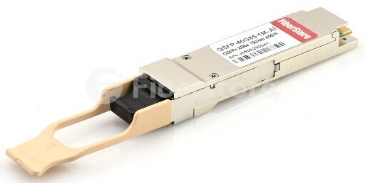
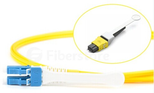
Conforming to the 802.3ba (40GBASE-LR4) standard, the 40G LR4 QSFP+ transceiver together with the LC connector can support an optical link length up to 10 kilometers over single mode fiber. For example, the following Juniper JNP-QSFP-40G-LR4 compatible 40GBASE-LR4 QSFP+ transceiver offers 4 independent transmit and receive channels, supporting link distance of 10 km over single mode fiber. In the process of transmitting, this kind of transceiver has to introduce MUX/DEMUX to multiplex/de-multiplex optical signals.

JNP-QSFP-40G-LR4

The working principle of this kind of QSFP+ transceiver is : in the transmit side, four 10 Gbp/s serial data streams are passed to laser drivers. The laser drivers control directly modulated lasers (DMLs) with wavelengths. the output of the four DMLs are optically multiplexed to a single-mode fiber through an industry-standard LC connector. In the receive side, the four 10 Gbp/s optical data streams are optically de-multiplexed by the integrated optical demultiplexer; then, each data steam is recovered by a PIN photodetector/transimpedance amplifier and passed to an output driver.

40G SR4 QSFP+ Transceiver

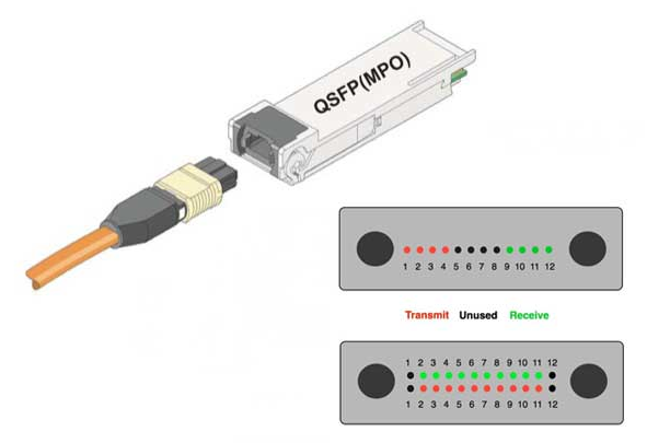
The 40G SR4 QSFP+ transceiver, conforming to the 802.3ba (40GBASE-SR4) standard, provides a 40G optical connection using MPO/MTP fiber ribbon connectors. Unlike the 40G LR4 QSFP+ transceiver, this kind of transceiver are used together with multi-mode fiber, supporting with a link length up to 100 meters on OM3 cable and 150 meters on OM4 cable.

The operating principle of the 40G SR4 QSFP+ Transceiver is : the transmitter convertsparallel electrical input signals into parallel optical signals through the use of a laser array. Then the parallel optical signals are transmitted parallelly through the multi-mode fiber ribbon. Reversely, the receiver converts parallel optical input signals via a photo detector array into parallel electrical output signals.

40G LR4 Parallel Single Mode (PSM) Transceiver

40G PSM transceivers are used to provide support for up to four 10Gb Ethernet connections on a QSFP+ port over single mode fiber. These transceivers support distance of up to 10 kilometers over single mode fiber using an 8 parallel fiber MPO interface. Each fiber pair can be broken out to a 10Gb Ethernet connection, compatible with up to four 10GBASE-LR interfaces. The MPO to 4 x LC single mode fiber patch cord can be used to breakout the 4 fiber pair of the MPO parallel connector to 4 separate fiber pairs.

Summary

To sum up, 40G SR4 QSFP+ transceivers are suitable for short-distance transmissions. So they are often used in data centers to interconnect two Ethernet switches with 12 lane ribbon OM3/OM4 cables. while 40G LR4 QSFP+ transceivers and 40G LR4 PSM transceivers are often used in long-distance transmission applications. Fiberstore offers a wide range of 40G QSFP+ transceivers, like 40GBASE-SR4, 40GBASE-LR4, 40GBASE-CR4 QSFP+ transceivers, etc. Besides, we also provide 40G direct attach cables, such as Juniper QFX-QSFP-DAC-1M, Cisco QSFP-4X10G-AOC3M and so on.

Guide to 40GBASE-SR4 QSFP+ Transceivers

Today’s enterprise data centers and networking environments are undergoing an infrastructure transformation, requiring higher speeds, greater scalability, and higher levels of performance and reliability to better meet the demands of business. As speed and performance needs increase, the 40GBASE-SR4 QSFP+ optical transceivers have become an integral part of overall system design. This article will give you a comprehensive introduction to 40GBASE-SR4 QSFP+ optical transceivers.

What Is 40GBASE-SR4 QSFP + Transceiver

40GBASE-SR4 is a fiber optic interface for multimode fiber of OM classes 3 and 4 with four parallel OM3 or OM4 fibers in both directions. “S” means short, indicating that it is an interface for short distances. The “R” denotes the type of interface with 64B/66B encoding and the numeral 4 indicates that the transmission is carried out over a ribbon fiber with four multimode fibers in every direction. Each lane has a 10 Gbit/s data rate. The 40GBASE-SR4 QSFP+ transceivers are hot-swappable, low-voltage digital diagnostic Ethernet optical transceivers that support high-speed serial links over multi-mode optical fiber at a signaling rate of 4×10 Gbps. They comply with QSFP+ mechanical, optical, and electrical specifications (SFF-8436). 40GBASE-SR4 QSFP+ modules usually use a parallel multimode fiber (MMF) link to achieve 40G. It offers 4 independent transmit and receive channels, each capable of 10G operation for an aggregate data rate of 40G over 100 meters of OM3 MMF or 150 meters of OM4 MMF. It primarily enables high-bandwidth 40G optical links over 12-fiber parallel fiber terminated with MPO/MTP multifiber female connectors.

QSFP-40G-SR

Applications of 40GBASE-SR4 QSFP + Transceiver

40GBASE-SR transceivers are used in data centers to interconnect two Ethernet switches with 8 fiber parallel multimode fiber OM3/OM4 cables. The QSFP+ transceiver modules can be connected to both copper and optical cables. In the process of transmitting data, the 40GBASE-SR4 QSFP+ transceiver converts parallel electrical input signals into parallel optical signals by a 850nm vertical cavity surface emitting laser (VCSEL) array. All data signals are differential and the data rate can be up to 10 Gbps per channel. For example, Extreme 10319 compatible 40GBASE-SR4 QSFP+ transceiver from Fiberstore operates in 4-lanes at a wavelength of 850nm.

QSFP-40G-SR4 vs. QSFP-40G-CSR4

40GBASE-CSR4 QSFP modules extend the reach of the IEEE 40GBASE-SR4 interface to 300 and 400 meters on laser-optimized OM3 and OM4 multimode parallel fiber, respectively. Each 10-gigabit lane of this module is compliant to IEEE 10GBASE-SR specifications. This module can be used for native 40G optical links over 12-fiber parallel cables with MPO/MTP female connectors or in a 4x10G mode with parallel to duplex fiber breakout cables for connectivity to four 10GBASE-SR interfaces. Cisco compatible QSFP-40G-CSR4 transceiver from Fiberstore is optimized to guarantee interoperability over the complete specification range of 10GBASE-SR.

Fiberstore offers a wide range options of brand-compatible 40GBASE-SR4 QSFP+ transceivers. In order to ensure each transceiver with high-compatibility, we have a comprehensive and reliable test assured program for each optics. All these 40GBASE-SR4 QSFP+ transceivers will be tested in the original-brand switches to guarantees the high compatibility.

Factors in Preparing for 40/100G Ethernet Migration

With the increased demands on data center throughput, 40/100G Ethernet is an integral component of today’s data center. The implementation of 40/100G Ethernet is dependent upon a variety of organizational factors, including existing infrastructure, budget, throughput demand and leadership priority. In this article, we will discuss the factors that need to be considered when preparing for 40/100G Ethernet migration.

Link distances and loss amounts

As data center speeds increase, optical loss budgets decrease. Optical loss occurs over cabling distance and at mating points where connections are made. Since most data center cabling runs are shorter distances (compared to long-haul campus runs), the inherent losses from distance in a data center are somewhat negligible compared to the losses incurred from mating points. As connections in the data center increase to improve manageability, performance suffers. This is because added connections contribute to increased dB loss. Thus, a balance must be maintained between manageability and performance.

Cabling infrastructure design

Recommended cabling infrastructure deployments in the data center are based on guidance found in Telecommunications Infrastructure Standard for Data Centers, or TIA-942. Cabling deployed in the data center today must be selected to support data rate applications of the future. Since parallel-optics technology requires data transmission across multiple fibers simultaneously, a multifiber (or array) connector is required. Using MPO-based connectivity in today’s installations is a simple and easy deployment. Starting with 10G, a 12-fiber MPO cable is deployed between the two 10G switches. Modules are used at the end to transition from the 12-fiber MPO to LC duplex. When it is with 40G, the use of a 12-fiber or 24-fiber MPO jumper is needed to establish connectivity between the switches.

Push-Pull MPO patch cable

Connectivity options

When migrating to 40/100G speeds, there are several connectivity options to consider when planning your cabling infrastructure. The first uses long-haul (LX) transceivers with single-mode (SM) cabling. Data is transmitted via serial transmission. In order to work effectively over long distances, the lasers used in LX transceivers are extremely precise and expensive. This drastically increases the overall cost of an LX/SM connectivity solution. The next option uses short-haul (SX) transceivers with multi-mode cabling. Data is transmitted via parallel optic transmission. Parallel optic transmission aggregates multiple fibers for transmission and reception. Taking the 40G SR4 transmission for example, Finisar FTL410QE2C compatible 40GBASE-SR4 QSFP+ transceiver operates in four channels over multi-mode cabling, four fibers transmitting at 10G each, while four fibers receiving at 10G each. This means a total of eight strands of fiber will be utilized for a 40G Ethernet channel.

Fiber types

If multi-mode cables are being used to migrate to 40/100G Ethernet, it is recommended they be OM3 or OM4 fiber, replacing any OM1 or OM2 fiber cables. OM4, the newest fiber type on the market, transmits the most bandwidth and is more effective over longer distances. OM4 is highly recommended for any new installs as it provides the longest lifespan in a cabling infrastructure.

In conclusion, in order to migrate your network to 40/100G Ethernet smoothly, you are supposed to consider all these factors that may influence comprehensively. Only when you evaluate your current cabling infrastructure and choose the right connectivity methods can you ensure a smooth and trouble-free migration.

40G and 100G Pluggable Optics in Data Center

In order to meet the demand for increased network bandwidth, migration to 40G Ethernet links for switch to server and storage area network connections in data centers and 100G Ethernet links for core switching and routing connections in the backbone is the trend.

The requirement for higher data rates is being driven by many factors. Switching and routing, virtualization, convergence and high-performance computing environments are examples of where these higher network speeds will be required within the data center environment. Additionally, Internet exchanges and service provider peering points and high-bandwidth applications, such as video-on-demand, will drive the need for a migration from 10- to 40- and 100-Gbit interfaces.

40G Pluggable Optics

There is various ideal equipment for 40 Gigabit Ethernet applications, such as cables, transceivers, connectors and switches for 40G transmission. For instance, OM3 and OM4 multimode fibers are widely used in 40 Gigabit applications especially in data centers. These cables have lower cost than singlemode fibers, for they can avoid higher costs created by single-mode laser source. The transceivers connected by cables is at the center of the 40 Gigabit Ethernet network layer. They are usually connected by OM3 or OM4 fibers and can be plugged into a variety of components including interface cards and switches or network servers. The common types of 40G transceivers are C Form-factor Pluggable (CFP) transceivers, and Quad Small-Form Pluggable (QSFP) transceivers. For example, Cisco QSFP-40G-CSR4 compatible QSFP+ transceiver supports link lengths of 82m, 300m and 400m, respectively, on OM2, OM3 and OM4 multimode fibers at a wavelength of 850nm.

JG325B

100G Pluggable Optics

100G is ready here. Tens of thousands of 100G Ethernet links deployed in core routers and carrier switches. Vast majority are CFP modules and CFP2 deployments are now starting. In addition,100G is rapidly expanding. For instance, new optical standards for the data center (100G SR4, CWDM4, PSM4) and new higher density 100G module form factors like CFP4 and QSFP28 are on the way. High port-count 100G switches are being designed and many 100G modules will be used to support high-density 10G and 25G. It is said that 100G and 4x 25G deployments are expected to grow substantially starting in 2015. 100G products mainly include 100GBASE-SR10 and 100GBASE-LR4 CFP/CFP2/CFP4 and 120G AOCs. Additionally, QSFP28 as the 100G module form factor of choice for new data center switches is also launched.

40G vs. 100G in the Data Center

The most direct difference of 40G and 100G optics is the data rate. But actually, 40G and 100G optics have their own merits.

Characteristic of 40G Pluggable Optics

  • Lowest cost per bit
  • MMF reaches up to 300 m
  • Breaks out to 4 x 10G

Characteristic of 100G Pluggable Optics

  • Highest density per bit
  • Lowest power consumption
  • MMF reaches up to 100m for now
  • Breaks out to 4 x 25GE
Conclusion

Content and application growth is driving the growth in bandwidth and traffic as well as growth in optical links. 40G and 100G optics developments are supporting the growth in traffic with smaller module form factors for higher port density with lower power consumption and lower cost per bit. Meanwhile, new link speeds like 25G, 50G, 200G and 400G are being standardized. The pluggable optics will continue to develop to further satisfy the changing requirements in data center.

Important Components for 40/100G Ethernet Migration

With the growth of bandwidth-intensive applications such as high-performance computing and business continuity, there emerge higher-speed networks of 40/100G Ethernet. And as products become less expensive and more available over time, 40/100G Ethernet will inevitably be commonplace in our daily life. Therefore, it is necessary to create a migration path by installing a structured cabling system that can support the future 40/100G networking needs. In this system, such fiber optic products as MTP/MPO assemblies, 40/100G transceivers and 40/100G direct attach cables (DACs) are important components. This article will discuss their roles in 40/100G Ethernet migration respectively.

MTP/MPO Assemblies

Since 40/100G Ethernet uses parallel optics technology which requires data transmission across multiple fibers simultaneously, the multi-fiber connectors are needed. MTP/MPO is the designated interface for multi-mode 40/100G Ethernet, and its backward is compatible with legacy 1G/10G applications as well. 40G Ethernet uses a 12 position MTP/MPO connector interface that aligns 12 fibers in a single row. And the 4 leftmost fibers are used to transmit data, the middle 4 fibers are left unused, while the 4 rightmost fibers are used to receive data. 100G Ethernet uses a 24 position MTP/MPO connector with two rows of 12 fibers. And the outermost fibers on either end of the rows are vacant, while 10 fibers in the upper row for transmitting data and the remaining 10 fibers in the lower row for receiving data.

optical lane assignments

40/100G Transceivers

Together with MTP/MPO connectors, 40/100G transceivers are often used (as shown in the above figure). Through the use of plug-and-play, hot-swap transceiver miniaturization, fiber connectivity in higher-speed active equipment is being condensed and simplified. Transceivers used in 40/100G Ethernet migration include 40G QSFP+ transceivers, 100G CFP transceivers and so on. 40G QSFP+ transceivers can support 4x10G modes, which allow new parallel optics active equipment being compatible with existing 10G transceivers. And the electrical connection of a 100G CFP transceiver uses 10x10G lanes in RX (receive) and TX (transmit) direction, supporting both 10x10G and 4x25G variants of 100G interconnects.

40/100G DACs

To save cost, 40/100G DACs are often used in 40/100G Ethernet instead of optical transceivers. Applied to short reach applications, it is a fixed assembly supporting high speed data that uses a small form-factor connector module as an optical transceiver on each end of a length of cable. The modules on each end meet small form-factor standards and have some function of the optical transceivers, meaning that DAC inherits some advantages of the small form-factor module. Thus, sometime there is no need to upgrade the equipment by using a DAC.

To meet the future 40/100G networking needs, the cabling system shall include components that not only support future high-bandwidth applications but also be compliant to 1G and 10G applications and all current and anticipated industry standards. Meeting all these requirements, the above mentioned MTP/MPO connectors, 40/100G transceivers and 40/100G DACs play important roles in migration to 40/100G Ethernet. As a professional supplier of fiber connectivity network solutions, Fiberstore supplies all these fiber optic products and other kinds of products for 40/100G Ethernet migration.