Transport and Aggregation Networks Solutions for Optical Amplifiers

Transport and aggregation network design

Network operators have the common basic target to produce cost-efficient telecommunication services. When considering operators from different nations including carriers operating worldwide, a variety of network architecture designs need to be considered. The suitable network design depends on the individual national properties with respect to the telecommunication services to be provided, such as the local population density distributions, the characteristic local residential consumer behavior, for example, the demand for voice telephony, internet protocol, or broadband TV, or the distribution and service level agreement (SLA) requirements of the business customers. The design of the network is governed by the topology. DWDM network for example, ring, star, mesh, by the purpose (access, aggregation, transport), by the mean and maximum link distance, and by the density and degree of switching or grooming nodes. All this has a direct impact on the choice of amplification in the optical multiplex section (OMS) of DWDM systems and on the local placement of DWDM optical amplifiers.

13dBm 1550nm CATV EDFA Fiber Optic Amplifier

The diameter of networks is one of the most obvious distinctions. Nationwide networks in the United States follow engineering rules different from those applicable to the national backbones in European countries, especially when the design of amplifier maps and the positioning of photonic cross connect (PXC)/ROADM based nodes are considered. The largest diameters within all optical transport is achieved in submarine cable networks that deploy lumped amplifier span designs with very short distance between adjacent DWDM EDFA and eventually supported by additional distributed Raman amplification.

Besides the distance, many other parameters influence decisions for special network layouts, such as the local distribution of population and industry to be connected, the traffic patterns and capacity evolution, the telecommunication service kinds and classes, and much more. Also, the deployment choice of lumped inline amplifiers . distributed Raman amplification or hybrid schemes, gain equalizing devices, electrical or optical inline regenerators, and electrical grooming nodes or optically amplified multi degree ROADM nodes is strongly dependent on these multiple factors.

The research shows that some network options with consequences for optical amplifier applications will be described against the background of European national network. Here a variety of requirements force operators to select many different network architectures for different local domains with suitable primary foci to meet optimum transport efficiency and operational performance. The present trend is to consolidate different network domains into a converged platform to simplify the overall network management process.

European networks cover many scenarios of possible architectures, for ultra long-haul (ULH) pan-European backbone to national European backbone, metro, and access networks. The typical distance characteristics of link lengths between major backbone nodes for North America and pan-European networks, but the distance are significantly shorter. The backbone links of national networks of the different European states like Germany reference network. Here the mean fiber link distance between major between major cities and thus backbone nodes is about 400 km which could be still called “metro”. However, as for the next generation architecture it is intended to intensively apply optically transparent transmit nodes (ROADM/PXC), future national networks will also demand systems with a longer reach. In the following sub-sections we will focus on typical modern intranational European network architectures.

Future converged telecommunication platforms will comprise access, aggregation, and transport networks. Their design rules depend on their primary purpose: either traffic aggregation or distribution from and to customers, or the transport and routing of large amounts of combined capacity.

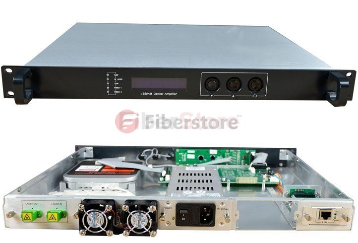
Fiberstore store is specialized in optical fiber products, DWDM optical fiber amplifier is one of their main product categories, if you want to learn more about the DWDM, welcome to visit our online shop. http://www.fiberstore.com

How the PON Networking infrastructure Support the delivery of the Internet Services

Telecommunications networks are hierarchy organization. House and commerce access is based on wireless and wireline, wireless networks include 2G, 3G, 4G and WiFi, and wireline technologies are those fiber point-to-point (P2P), point-to-multipoint passive optical networks (PONs), copper twisted pair, HFC (hybrid fiber coaxial)  technologies.

Passive optical networks are the basis of Optical Access Networks (OANs) as defined in ITU-T Recommendation G.902, and also of hybrid fiber coaxial networks. PONs are often configured in tree or bus structures. Feeder and distribution fibers, together with the distribution elements in the outside plant, are referred to as Optical Distribution Network (ODN). The different degrees of optical versus electrical access down to the customers for the different fiber-to-the-X(FTTX) access scenarios, where X stands for cabinet (Cab), curb (C), building (B), or home (H). The reference points for the OAN are the service network interface (SNI) and the user network interface (UNI). They are defined in ITU-T Recommendation G.983. The network architecture used to build a PON based FTTx network will typically comply with international standards.

The main PON components include just like, OLT which its full name is Optical line termination and service provider head end in CO, and Remote node just called RN , it mostly passive, containing splitter/combiner or filter, for example, in cabinets, then ONU, it is optical network unit where at customer premises (CP), or in cabinet, etc.

AG.983 compliant PON typically consists of an optical line termination (OLT), which is located at the IPTV data center and a number of optical network terminals (ONTs), which are installed at the end users premises. Note that ONTs May also be installed at different neighborhoods where the optical fiber terminates. In these situations, high speed copper data transfer technologies such as DSL are used to carry the IPTV signals into the end-users’ household.

The OLT uses components such as fiber cable and optical splitters to route network traffic to the ONTs.

Fiber cable, the OLT and the various ONT’s are interconnected by fiber optic cabling. With few transmission losses, low interference, and high bandwidth potential, optical fiber is an almost ideal transmission medium. The core of the fiber optic cable is made of glass and carries data in the form of light wave signals. The diameter of the fiber cable is relatively small and is designed to allow network engineers splice the cable at various locations along the physical route. The purity of today’s glass fiber, combined with improved system electronics in the cable, permits the transmission of high speed services over long distances. In fact, the G.983 standard allows the PON to carry digitized light signals up to a maximum distance of 20 km without amplification.

Optical splitters, the optical splitter are used to split a single optical signal into multiple signals. It achieves this function while not altering the state of the signal; in other words, it does not convert it to electrical pulses. Optical splitters are also used to merge multiple optical signals back into a single optical. These splitters allow up to 32 households to share the FTTx network bandwidth and are typically housed in accessible mechanical closures.

In PONs, several customers are connected to a central office or local exchange via a passive fiber-optic infrastructure. This infrastructure splits into single-mode fibers and passive splitting components (power splitters/combiners and/or WDM filters). PONs work bidirectionally on single fibers, in almost all cases, by using different wavelengths for upstream (US) and downstream (DS).

Fiber cable and optical splitters are “passive” optical components. The use of passive components to guide the light waves through the network eliminates the need for remote powering, which cuts down on operational and maintenance costs.

The main purpose of the ONT is to provide IPTV subscribers with an interface to the PON. It receives traffic in optical format, examines the address contained within the network packets, and converts it into electrical signals. The ONT can be located inside or outside the residence, and is typically powered from a local source, and include bypass circuitry that allows the phone to operate normally in the event of a power failure. The majority of ONTs will include an Ethernet interface for data traffic, an RJ-11 connection for connecting into the home phone system, and a coaxial interface to provide connectivity to the TV. The ONT is also responsible for converting data into optical signals for transmission over the PON. active optical networks (AON) makes use of electrical components between the IPTV end user and the data center. In particular, the AON networking architecture utilizes Ethernet switches that reside between the IPTV data center and the endpoint of the fiber network.

For example, a single piece of optical fiber is run from the backend office to an optical splitter, which is typically located in close proximity to the subscriber’s house. The bandwidth on this fiber is typically shared and is capable of supporting high bandwidth capacities ranging from 622 Mbps all the way up to several gigabytes of data per second.

IPTV FTTH

In addition to the physical components of a PON also illustrates the transmission of three different light wavelengths (channels) over the network. The first wavelength is used to carry high speed Internet traffic. The second wavelength is allocated to carry IO video services and the third wavelength may be used to carry interactive traffic from the subscriber’s home network back to the service provider’s backend equipment. Specialized FTTX filters called wavelength division multiplexers (WDMs) are installed at the data center and inside the OLT that allow a PON to support the transmission of multiple parallel channels or wavelengths on the one piece of fiber. Thus, creating a number of virtual fiber channels over a single fiber pair. Under WDM, the capacity of the network is increased by assigning signals that originate from optical sources to specific wavelengths on the optical transmission spectrum.

Fiberstore supply high quality PON & AON System products, like OLT, ONU with low price. Welcome to visit our online store. http://www.fiberstore.com/

Article Source: http://www.fiber-optical-networking.com/

The Introduction of CWDM Systems Access and Backhaul

Coarse WDM systems have been in wide use for metropolitan area backhaul and business access since the very beginning of the twenty-first century. They are based on up to 18 CWDM channels spaced 20 nm in the wavelength region 1270-1610 nm, as defined in ITU-T Recommendation G.694.2. In the beginning, CWDM price had the advantage of being cheaper than DWDM price since CWDM components do not requirement temperature control or stabilization. This advantage is expected to decrease since CWDM transceivers are not wideband tunable. DWDM transmitters, on the other hand, are full-band tunable. This allows cost reduction in manufacturing since only a single type of transmitter needs to be produced. It also allows operational cost reductions, since, for example, sparing and also network planning are greatly simplified.

In many cases, CWDM was used for (DSLAN, GPON, wireless 2G/3G) backhaul, running one or multiple GbE services per wavelength. Up to 4GbE signals can be multiplexed at wire speed (after 10B/8B decoding) onto muxponders running at 4.3Gb/s. In CWDM backhaul, this bit rate is relevant because it has similar cost than 2.5 Gb/s. This low cost ws originally driven by transmission of 4Gb/s Fibers Channels(FC) signals. In general DWDM transmission, 4Gb/s per channel is almost irrelevant due to its lack of spectral efficiency. Capacity increase up to 16 x 10 Gb/s has also been demonstrated with CWDM.

Backhaul topologies are often rings, a four-node CWDM ring with a hub node and three optical add-drop multiplexer (OADM) sites. For monitoring purposes, the OADMs can be connected to a network operations center (NOC) via an embedded communication channel (ECC). The ECC can transport narrowband management information.

CWDM systems often use CWDM-colored small form-factor pluggables (SFPs)  as remote interfaces. These can be accommodated directly in the client systems, or on transponders/muxponders. Per-channel bit rates of 1.25-4.3 Gb/s are covered (where 4.3 Gb/s share the transceiver technology with 4G Fiber Channel, which is one of the drivers behind the advantageous economics). Ten gigabit per second CWDM-fixed-wavelength extended form-factor pluggables (XFPs) also exist, but are typically restricted to the wavelengths 1470-1610 nm. In effect, these pluggables are versions of the respective DWDM transceivers, and, hence, unlike their lower bit rate counterparts, do not have significant cost advantages. Consequently, their relevant specifications are similar to the DWDM XFP specifications. So far, dedicated CWDM 40 or 100 Gb/s transceivers have not been built, and it is unlikely this will ever happen. For 4 and 10 Gb/s, reduced chromatic dispersion (CD) allowance and also power budget must be considered. This may limit maximum reach, without added means like CD compensation (not commonly used in CWDM systems), or forward error correction (FEC) to < 60 km.

DWDM xfp

Typically, in CWDM systems, effects of polarization-mode dispersion (PWD), polarization-dependent loss (PDL), and nonlinearity are covered within the transceiver specifications, due to distance limitations. If link lengths approach the respective specified CD limits, power budget penalties in the 1dB range may have to be applied.

FiberStore designs, manufactures, and sells a broad portfolio of optical communication products, including passive optical network, or PON, subsystems, optical transceivers used in the enterprise, access, and metropolitan segments of the market, as well as other optical components, modules, and subsystems. If you have trouble in these aspects, you can visit our fiberstore. http://www.fiberstore.com/

Article Source: http://www.fiber-optical-networking.com/