Talking about the comparison between CWDM and DWDM

CWDM, just as DWDM, use multiple light wavelengths to transmit signals over a single optical fiber. However, there are still some differences betwwen the two techologies in many ways.

CWDM uses a 20-nm wavelength spacing that is much wider than the 0.4 nm for DWDM. The wider wavelength spacing in CWDM means lower product development costs. This is one reason why CWDM is less costly than DWDM.

Most CWDM devices operate in the 1470-nm to 1610-nm range. The frequency grid for DWDM and the wavelength grid for CWDM systems are defined by the international telecommunication union (ITU) standard G.694.1 and G.694.2, respectively.

CWDM provides a maximum of 8 lambadas between two CWDM multiplexers over a single fiber pair as compared to DWDM Multiplexers, which support up to 32 lambdas (based on 0.8-nm or 100-GHz wavelength spacing) over a single fiber pair. some long-haul DWDM systems can support up to 160 lambdas per fiber pair.

Each CWDM channels uses a specialized gigabit interface converter (GBIC) or small form-factor pluggable (SFP) transceivers are commonly known as colored GBIC and SFP. Each CWDM channels uses a different “color” GBIC or SFP because each lambda represents a different color in the spectrum. In this case, the native GBIC or SFP in the client devices are substituted with a colored GBIC or SFP.

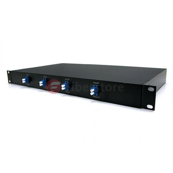
CWDM multiplexers are usually passive (i.e, not powered) devices containing a very accurate prism to multiplex eight separate wavelengths of light along a single fiber pair. And passive CWDM devices cannot generate or repeat optical signals.

No amplification is possible with CWDM because CWDM uses wavelengths that cannot be amplified with EDFA amplifiers. Therefore, the maximum distance for a CWDM link is approximately 100 km.

The Cisco ONS 15501 EDFA, which has a wavelength range of 1530 nm to 1563 nm, can only amplify two signals (1530 nm and 1550 nm) out of the eight signals that are multiplexed onto the fiber pair.

CWDM provides an alternative solution to DWDM for low-latency and high-bandwidth requirements associated with synchronous replication application. However, DWDM is more scalable than CWDM. DWDM also has a longer distance capacity than CWDM because DWDM can be amplified. The main benefit of CWDM is its low cost. It is a cheaper solution than DWDM. In other words, CWDM is optimized for cost, while DWDM is optimized for bandwidth. For enterprises that have access to dark fiber and have only limited scalability requirement, CWDM is a relatively inexpensive way to achieve low-latency and high-bandwidth interconnections between DCs. The CWDM implementation also results in less complex installation, configuration, and operation as compared to DWDM.

CWDM can be deployed in point-to-point, linear, or fiber protected ring topologies, It is limited to a distance of up to 120 km for Gigabit Ethernet and 100 km for 2-G FC in a point -to-point topology. It is typically used only for extension of the FC fabric in a metro or campus application. As CWDM carries only eight lambdas on a single fiber pair, there are limits to the number of possible drops and the number of sites that can be interconnected. A ring or linear topology reduces the distance depending on the number of OADMs traversed by the CWDM channels because each CWDM OADM introduces additional power loss in the network.

CWDM OADM

CWDM can also be used to enable multiple ISL connections between the switches over a single fiber since it requires less fiber for interconnecting two metro sites. The same benefit applies to port channel implementation between the switches.

In short, DWDM is a solution that provides a higher number of connections and longer reach, or extension, at a much higher cost while CWDM is a more cost-effective solution for metro or campus solutions where the distance is limited.

If you have any questions about CWDM and DWDM technology, welcome to visit our online store. http://www.fiberstore.com/

Article Source: http://www.fiber-optical-networking.com/


The development of MPO optic fiber communication systems

In recent years, in order to adapt high speed and large capacity optical fiber communication systems the high density and high efficiency cabling connecting needs, there are two companies in Japan have developed and research in MTO or MTP fiber connectors.

Based on such as high speed and large capacity of DWDM optical fiber communication systems has a large number of using, fiber optic connector is an important part of DWDM technology although in the past single core SC connectors has been widely adopted. And recent years, the demand for multi-fiber high-density connector DWDM system has improved. Now the most popular 8 fiber mtp mpo connector sm optical density is about five times as the SC connectors. Optical fiber connector affect the reliability and the performance of optical transmission system.

When fiber optic cable introduced from outside, fiber optic cable need to be welded in the fiber cassette, is also called terminal box. while for example, fiber optic MPO cassette 12 fibers , with SC,LC,ST, FC connectors, is a highly flexible fiber management unit that can be used stand alone or integrated into the MPO fiber optic patch panels. And before this, MPO/MTP fiber optic patch cord need to connect optical transceiver and terminal box.

The new technology is that high-end pick density of MPO fiber system can increase the number of core optic fiber and the use of fiber optic connectors, no longer just 12 fibers or 24fibers, it might be 72 fibers. Then if we can accurately calculate the length of the fiber optic cable, we will save a lot of time.

multicore

MTP/MPO high-density wiring system will be high density optical fiber connector and the ribbon cable in the factory to complete the termination, testing, and equipment at the scene, plug and play, support the rapid deployment, user data center is the increasing data center under the background of high capacity wiring needs ideal solution, with simple installation, construction fast, compact design, high precision, plug and play, etc.

With the improving of the network speed, in terms of optical fiber, correlates twin-core fiber can support MB, gigabit application, but without the use of special coding and agreement, it is difficult to support the 40G and 100G two core optical fiber, and a single channel of 4 core or 10 core optical fiber, 40G and 100G in normal optical fiber communication networks just like the 8 core optical fiber and 20 core optical fiber, it brought more challenge to the traditional data communication , so we will need to use high-density optical fiber. and except that, the important reason is the familiar optical fiber connectors, such as SC, LC no matter from some conclusions and miniaturization can satisfy the high-speed Internet standards are defined in the MDI multi-fiber requirements, and completing single fiber of multi-fiber links live is very difficult, because of a core of unqualified means the whole root is unqualified.

If you have any problem about optic fiber communication products, welcome to visit our store.Here is the website. http://www.fiberstore.com/

Article Source: http://www.fiber-optical-networking.com/


Using Fiber Optic Patch Cords to connect

Fiber-optic broadband access as a mainstream way to communicate with a large capacity, long-distance relay, good performance, adaptable, small size, light weight, low raw material prices and other advantages of wide sources confidential, the future of broadband Internet access applications can be expected to be very extensive. When we use the access fiber to the city, we have to apply to the fiber jumpers, fiber optic patch cords from the device used to make the fiber optic cabling link. Has a thick layer of protection, generally used in the connection between the Optical and terminal box.

Like the RJ-45 as easily, 3M VolitionVF-45 jacks and vf45 fiber patch cord are the latest fiber-optic network to the desktop duplex fiber optic interconnection, VF-45 plug and socket 8-pin modular jacks work like like to bring fiber applications and RJ simplicity of the interface as -45. VF-45 socket wiring board can be terminated on site and building horizontal cabling between telecommunications, takes less than one minute, two-core fiber can be terminated.

FC-FC Duplex 10G OM3 50125 Multimode Fiber Patch Cable

Fiber optic patch cords from the device used to make the fiber optic cabling link. Has a thick layer of protection, generally used in the connection between the Optical and terminal box. And press the connector fiber optic patch cords can be divided into: FC patch cords, ST patch cords, SC patch cords, LC patch cords, MU patch cords, MPO/MTP fiber optic patch cord , E2000 patch cords, MTRJ patch cords, SMA patch cords, etc.

The physical connection between the connecting hardware and the high-speed LAN/WAN or telecommunications equipment is through fiber optic patch cords. fiber optic patch cords are used to facilitate fast and easy moves, changes, or additions to the high-speed LAN/WAN at the wiring closet. They also make the connection to user equipment such as high-speed LAN/WAN interface cards at the desktop.

It is debatable whether patch cables can be considered a part of the structured wiring system. By definition, they are not because their use changes as the needs of the high-speed LAN/WAN users change. But they are so well defined by the ANSI/TIA/EIA-T568-A standard that it is an easy intellectual jump to include them in any dicussion of structured wiring.

You should not minimize the quality and performance of the patch cables you use for connecting to your patch panels and wall plates. They are as important as any other component in your structured cabling system.

Patch cord, by their very nature, are intended to be moved and flexed. For this reason, patch cables should be made from cable with stranded conductors, which offer a much greater flex life and are better suited for this application than solid conductors. Fiber jumpers and jumper twisted pair is the same use, multi-turn for the wiring. Changing the direction of the line layout. Because jumpers softer than light. And folding high.

You must take into account the length of the patch cables when planning your installation. As stated earlier, the maximum horizontal cable run cannot exceed 90 meters (285 feet). In addition, the EIA/TIA T568 standard allows for a maxium patch cable length of six meters (20 feet) in the wiring closet and three meters (ten feet) at the workstation outlet. The main horizontal cable run must be reduced by the excess amount so as not to exceed an overall length of 100 meters, including both horizontal cabling and patch cables if either of these lengths is exceeded. Another decision you will need to make concerning patch cables is whether to purchase them preassembled or to built them yourself. On the surface, building your own may seem like a way to save money, but of all the components in a structured wiring system, patch cables are probably the most difficult and time-consuming to assemble.

You will need three things to assemble your own patch cords: the proper cable, the proper connectors, and the proper crimp tool. The cable you choose must meet all of the mechanical, electrical, and performance specifications of the cable. In addition, you shoud choose the cable type and color based on the previous discussion.

If you are interested in using fiber optic, welcome to our fiberstore to buy related products, such as fiber optic cable, fiber optic connectors, fiber optic jumpers, etc. and even you can buy online. http://www.fiberstore.com/

Article source:http://www.fiber-optical-networking.com/